INSTALLATION INSTRUCTIONS
106495B1
WARNING
DISCONNECT POWER TO THE OPERATOR BEFORE AND DURING INSTALLATION OF THIS ACCESSORY. DO NOT RECONNECT POWER TO OPERATOR UNTIL INSTRUCTED TO DO SO. ENSURE DOORWAY IS CLEAR BEFORE STARTING TESTING OF UNIT.
STEP 1: Choose a convenient location that does not interfere with the normal opening and closing operation of your door or gate, such as on the door jamb or on the outside wall adjacent to the door jamb. Please keep in mind that some doors will swing outward in their travel, and could damage an improperly located keypad. Try your door first to ensure there is no possibility of interference.
MOUNT YOUR KEYPAD A
MINIMUM OF 5 FEET ABOVE THE
GROUND TO KEEP IT OUT OF
REACH OF CHILDREN.
STEP 2: Choose your mounting hardware. The screws provided are adequate for mounting your keypad directly into wood or similar material.
STEP 3: Drill a 3/32 inch pilot hole to a depth of
Figure 1
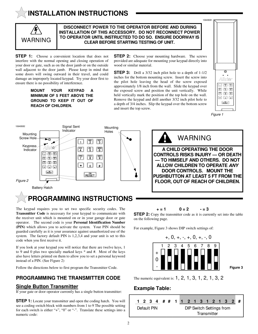
106495B2 | Signal Sent | Mounting |
|
| |
Mounting | Indicator | Holes |
|
| |
Screw Hole |
|
|
Keypress |
|
|
Indicator |
|
|
Figure 2
Battery Hatch
 PROGRAMMING INSTRUCTIONS
WARNING
A CHILD OPERATING THE DOOR
CONTROLS RISKS INJURY — OR DEATH
—TO HIMSELF AND OTHERS. DO NOT ALLOW CHILDREN TO OPERATE ANY
DOOR CONTROLS. MOUNT THE
PUSHBUTTON AT LEAST 5 FT FROM THE FLOOR, OUT OF REACH OF CHILDREN.
The keypad requires you to set two specific security codes. The Transmitter Code is necessary for your keypad to communicate with the receiver unit which is mounted on or in your garage door or gate operator. The second code is your Personal Identification Number (PIN) which allows you to activate the system. Your PIN should be guarded carefully as it is your assurance against unauthorized use of the system. The factory default PIN is 1,2,3,4 and your unit is set to this code when you first receive it.
+ = 1 | 0 = 2 | - = 3 |
STEP 2: Copy the transmitter code as it is currently set into the table on the following page.
For example, Figure 3 shows DIP switch settings of:
+, 0, +, -, +, 0, +, -, 0
If you look at your keypad you will notice that there are twelve keys, 1 to 9 and 0 plus two specially marked keys * and #. Most of the keys also have letters printed on them to allow you to set a personal keyword instead of a PIN. (See Figure 2)
Follow the directions below to first program the Transmitter Code.
PROGRAMMING THE TRANSMITTER CODE
Single Button Transmitter
If your gate or door operator currently has a single button transmitter:
STEP 1: Locate your transmitter and open the coding hatch. You will see a coding switch block with numbers from 1 to 9 The possible setting for each switch is either “+”, “0” or
1 | 2 | 3 | 4 | 5 | 6 | 7 | 8 | 9 |
|
| |||||||||||
| + |
|
|
|
|
|
|
|
|
|
|
|
|
|
|
|
|
|
|
|
|
|
|
|
|
|
|
|
|
|
|
|
|
|
|
|
|
|
|
|
|
| |
| 0 |
|
|
|
|
|
|
|
|
|
|
|
|
|
|
|
|
|
|
|
|
| - |
|
|
|
|
|
|
|
|
|
|
|
|
|
|
|
|
|
|
| Figure 3 |
|
|
|
|
|
|
|
|
|
|
|
|
|
|
|
|
|
|
|
| ||
|
|
|
|
|
|
|
|
|
|
|
|
|
|
|
|
|
|
|
|
|
|
The numeric equivalent is: 1, 2, 1, 3, 1, 2, 1, 3, 2
Example Table:
1 2 3 4 # # 1 1 2 1 3 1 2 1 3 2 #
Default PIN | DIP Switch Settings from |
| Transmitter |
2