Operating Manual 6125A and 4200A
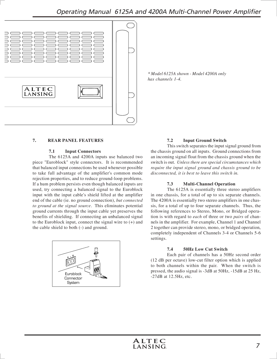
* Model 6125A shown - Model 4200A only has channels
7.REAR PANEL FEATURES
7.1Input Connectors
The 6125A and 4200A inputs use balanced two piece "Euroblock" style connectors. It is recommended that balanced input connections be used whenever possible to take full advantage of the amplifier's common mode rejection properties, and to reduce
7.2Input Ground Switch
This switch separates the input signal ground from the chassis ground on all inputs. Ground connections from an incoming signal float from the chassis ground when the switch is out. Unless there are special circumstances which require the input signal ground and chassis ground to be disconnected, it is best to leave this switch in.
7.3Multi-Channel Operation
The 6125A is essentially three stereo amplifiers in one chassis, for a total of up to six separate channels. The 4200A is essentially two stereo amplifiers in one chas- sis, for a total of up to four separate channels. Thus, the following references to Stereo, Mono, or Bridged opera- tion is with regard to each of three or two pairs of chan- nels in the amplifier. For example, Channel 1 and Channel 2 together can provide stereo, mono, or bridged operation, completely independent of Channels
+- G![]()
Euroblock
Connector
System
|
|
| 7.4 | 50Hz Low Cut Switch |
|
|
| ||
|
|
| ||
|
|
| Each pair of channels has a 50Hz second order | |
|
|
| (12 dB per octave) | |
|
|
| to both channels within the pair. When the switch is | |
|
|
| pressed, the audio signal is | |
+ - G | ||||
7