Operating Manual 6125A and 4200A
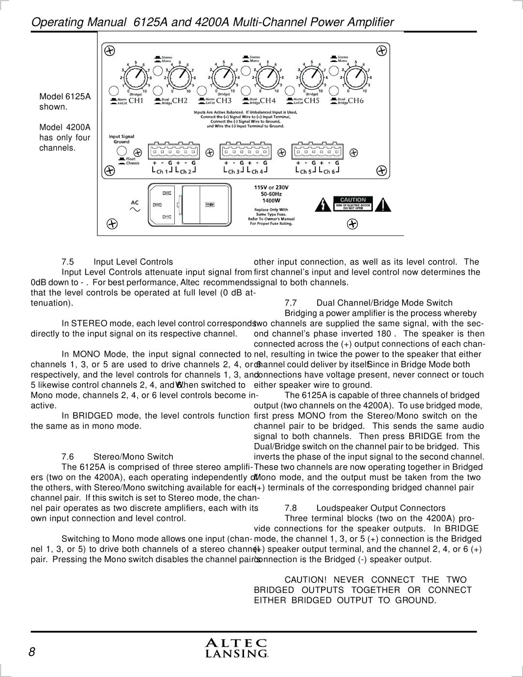
Model 6125A shown.
Model 4200A has only four channels.
7.5Input Level Controls
Input Level Controls attenuate input signal from 0dB down to
In STEREO mode, each level control corresponds directly to the input signal on its respective channel.
In MONO Mode, the input signal connected to channels 1, 3, or 5 are used to drive channels 2, 4, or 6 respectively, and the level controls for channels 1, 3, and 5 likewise control channels 2, 4, and 6. When switched to Mono mode, channels 2, 4, or 6 level controls become in- active.
In BRIDGED mode, the level controls function the same as in mono mode.
7.6Stereo/Mono Switch
The 6125A is comprised of three stereo amplifi- ers (two on the 4200A), each operating independently of the others, with Stereo/Mono switching available for each channel pair. If this switch is set to Stereo mode, the chan- nel pair operates as two discrete amplifiers, each with its own input connection and level control.
Switching to Mono mode allows one input (chan- nel 1, 3, or 5) to drive both channels of a stereo channel pair. Pressing the Mono switch disables the channel pair's
other input connection, as well as its level control. The first channel's input and level control now determines the signal to both channels.
7.7Dual Channel/Bridge Mode Switch Bridging a power amplifier is the process whereby
two channels are supplied the same signal, with the sec- ond channel's phase inverted 180°. The speaker is then connected across the (+) output connections of each chan- nel, resulting in twice the power to the speaker that either channel could deliver by itself. Since in Bridge Mode both connections have voltage present, never connect or touch either speaker wire to ground.
The 6125A is capable of three channels of bridged output (two channels on the 4200A). To use bridged mode, first press MONO from the Stereo/Mono switch on the channel pair to be bridged. This sends the same audio signal to both channels. Then press BRIDGE from the Dual/Bridge switch on the channel pair to be bridged. This inverts the phase of the input signal to the second channel. These two channels are now operating together in Bridged Mono mode, and the output must be taken from the two
(+) terminals of the corresponding bridged channel pair
7.8Loudspeaker Output Connectors Three terminal blocks (two on the 4200A) pro-
vide connections for the speaker outputs. In BRIDGE mode, the channel 1, 3, or 5 (+) connection is the Bridged
(+)speaker output terminal, and the channel 2, 4, or 6 (+) connection is the Bridged
CAUTION! NEVER CONNECT THE TWO BRIDGED OUTPUTS TOGETHER OR CONNECT EITHER BRIDGED OUTPUT TO GROUND.
8
