DA1921SX specifications
The Altinex DA1921SX is an innovative and versatile audio-visual distribution amplifier designed to meet the demands of modern AV systems. This unit is particularly well-suited for applications in corporate environments, educational institutions, and large event venues, where high-quality signal distribution is paramount.One of the main features of the DA1921SX is its ability to handle a variety of signal types, including HDMI, DVI, and VGA. This versatility ensures compatibility across a range of devices, making it an ideal choice for installations that require the integration of different technologies. The device supports resolutions up to 1920x1200, ensuring that the visual output is sharp and clear regardless of the source material.
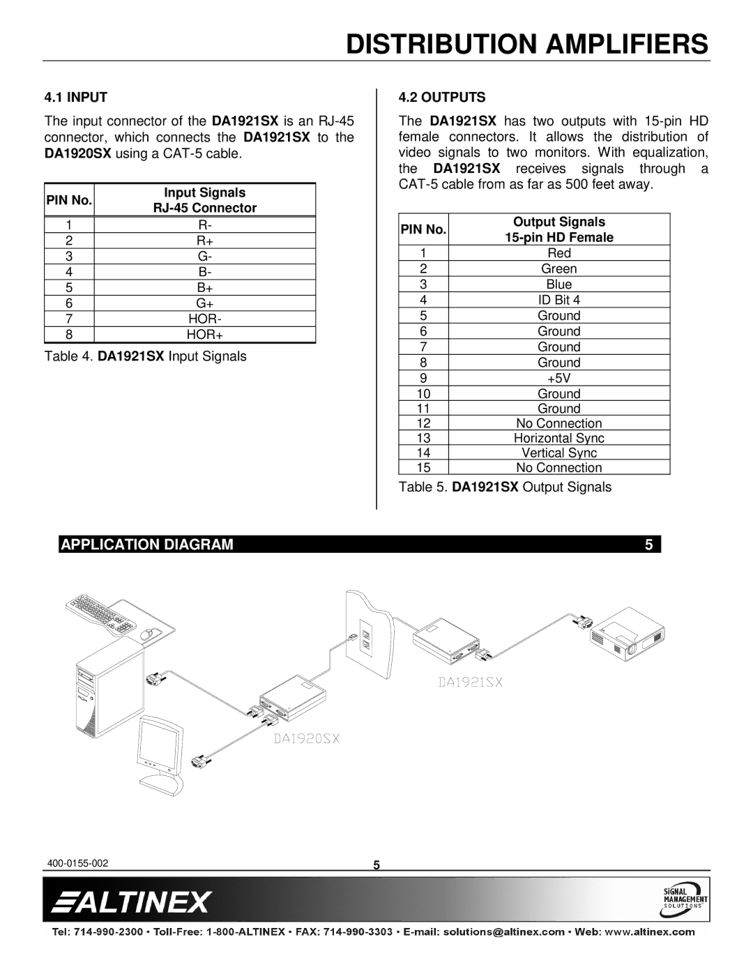
The DA1921SX offers a robust two-output format, allowing users to send the same video signal to multiple displays without signal degradation. This is particularly advantageous in settings like conference rooms, where presentations may need to be viewed on various screens. The unit is designed with advanced equalization and signal amplification technologies, which enhance the quality of the signal over longer distances.
In terms of connectivity, the DA1921SX features a wide range of input and output options, including a built-in loop-out port. This allows users to cascade additional amplifiers if needed, further expanding the system's capabilities. Additionally, the device is equipped with an easy-to-navigate interface, making it user-friendly for both technicians and end-users.
Another significant characteristic of the DA1921SX is its compact design, which facilitates easy installation in diverse spaces. The unit's low-profile casing ensures that it can fit into tight racks or mountings without taking up excessive space. This thoughtful design is complemented by its durable construction, ensuring reliable performance in demanding environments.
The Altinex DA1921SX also integrates advanced signal management technologies such as automatic input detection and a built-in microprocessor for real-time monitoring and control. This ensures optimal performance and user convenience, reducing maintenance requirements.
In conclusion, the Altinex DA1921SX is a powerful and flexible solution for audio-visual signal distribution. Its combination of high-quality signal handling, versatile connectivity options, and user-friendly features makes it a standout choice for any organization looking to enhance its AV capabilities.