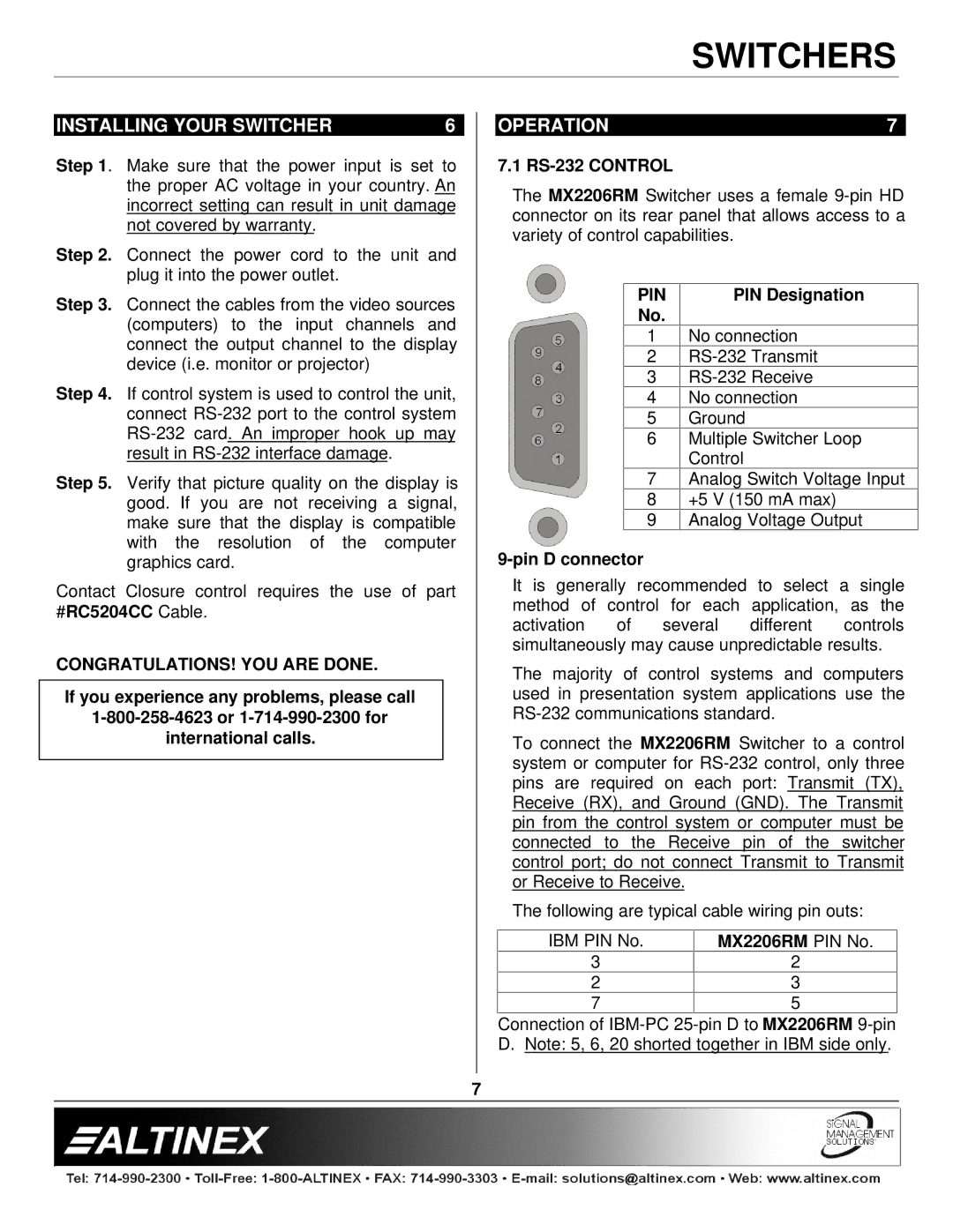
MX2206RM specifications
The Altinex MX2206RM is a sophisticated and innovative product designed to enhance the efficiency of AV systems, making it an essential tool for a variety of applications, ranging from corporate presentations to educational settings. This advanced multimedia interface serves as a reliable solution for managing multiple inputs and outputs, significantly simplifying the process of connecting devices to a centralized system.One of the key features of the MX2206RM is its robust support for a wide array of video and audio formats. This versatility allows users to seamlessly integrate diverse devices, including laptops, projectors, and display screens, without compatibility concerns. The MX2206RM supports HDMI, VGA, and audio connections, among others, ensuring that users can connect virtually any device with ease.
The product is equipped with a microprocessor-controlled design, enhancing its operational efficiency. This allows for intelligent switching between the various input sources, ensuring that the desired video or audio content is displayed without delay. The intelligent switching technology minimizes interruptions, making it ideal for live presentations and events where time is crucial.
The MX2206RM also features built-in equalization and signal amplification, which enhances the quality of the transmitted audio and video signals. These technologies are particularly beneficial in larger installations, where signal degradation can compromise performance. By ensuring that signals reach their destination without loss of quality, the MX2206RM maintains high standards for audiovisual output.
In terms of usability, the MX2206RM boasts a user-friendly interface that allows for quick and easy operation. The intuitive design makes it accessible for users of all levels of technical expertise. Additionally, the product can be controlled remotely, further enhancing its flexibility and convenience.
Another significant characteristic of the MX2206RM is its compact and rack-mountable design, which saves space while providing a professional appearance for installations. This design is particularly useful in conference rooms or educational environments where aesthetics are as important as functionality.
In conclusion, the Altinex MX2206RM is a powerful multimedia interface that combines versatility, intelligence, and user-friendly operation. Its advanced features and reliable performance make it an invaluable component for modern AV systems, catering to a wide range of professional and educational needs.

