TT499 Drawing Table “Caddy”
Assembly Instructions
No. TT499-1 White • No. TT499-2 Black
HARDWARE LIST
Key Qty. Description
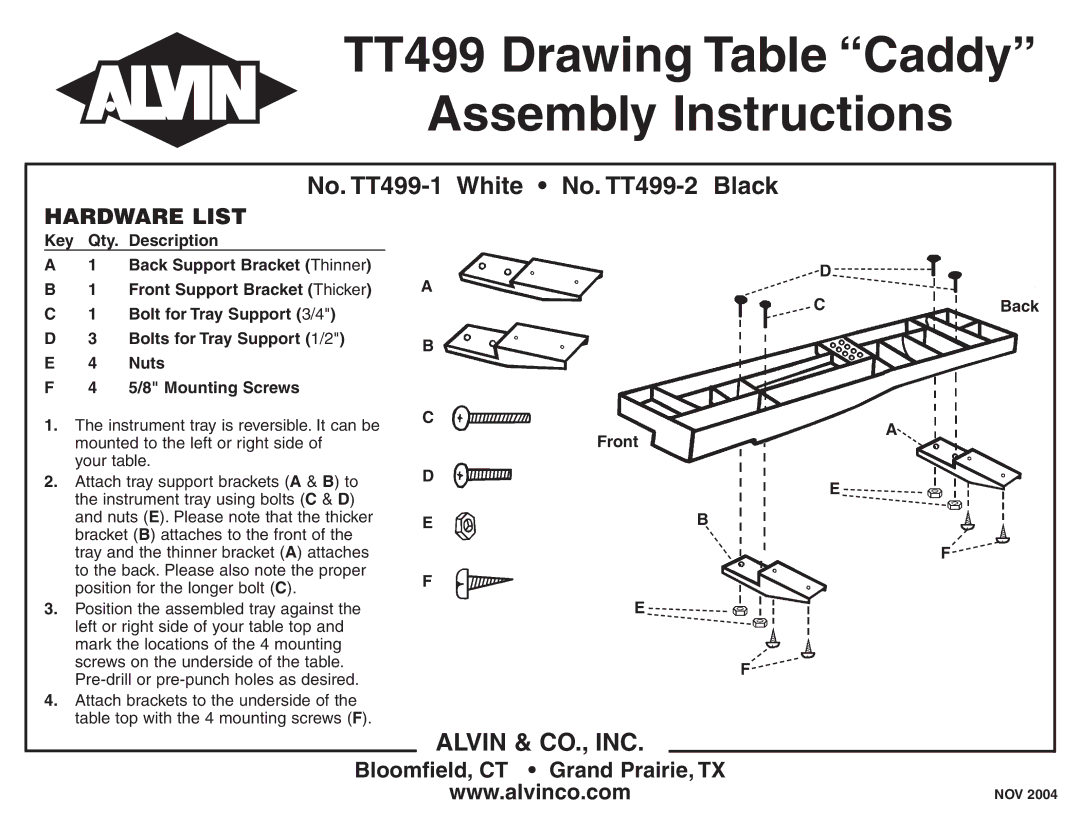
A1 Back Support Bracket (Thinner)
B1 Front Support Bracket (Thicker)
C1 Bolt for Tray Support (3/4")
D3 Bolts for Tray Support (1/2")
E | 4 | Nuts |
F | 4 | 5/8" Mounting Screws |
1. | The instrument tray is reversible. It can be |
| mounted to the left or right side of |
| your table. |
2. | Attach tray support brackets (A & B) to |
| the instrument tray using bolts (C & D) |
D![]()
![]()
A
CBack
B
C
A![]()
Front
D
E ![]()
![]()
and nuts (E). Please note that the thicker |
bracket (B) attaches to the front of the |
tray and the thinner bracket (A) attaches |
to the back. Please also note the proper |
position for the longer bolt (C). |
E ![]() B
B![]()
F
F![]()
3. | Position the assembled tray against the |
| left or right side of your table top and |
| mark the locations of the 4 mounting |
| screws on the underside of the table. |
| |
4. | Attach brackets to the underside of the |
| table top with the 4 mounting screws (F). |
E ![]()
![]()
F![]()
ALVIN & CO., INC.
Bloomfield, CT • Grand Prairie, TX
www.alvinco.com
NOV 2004