Titan Drafting Tables
Assembly Instructions
DRAFTING HEIGHT
W/ DRAWER
For WTB42, WTB48, WTB60,
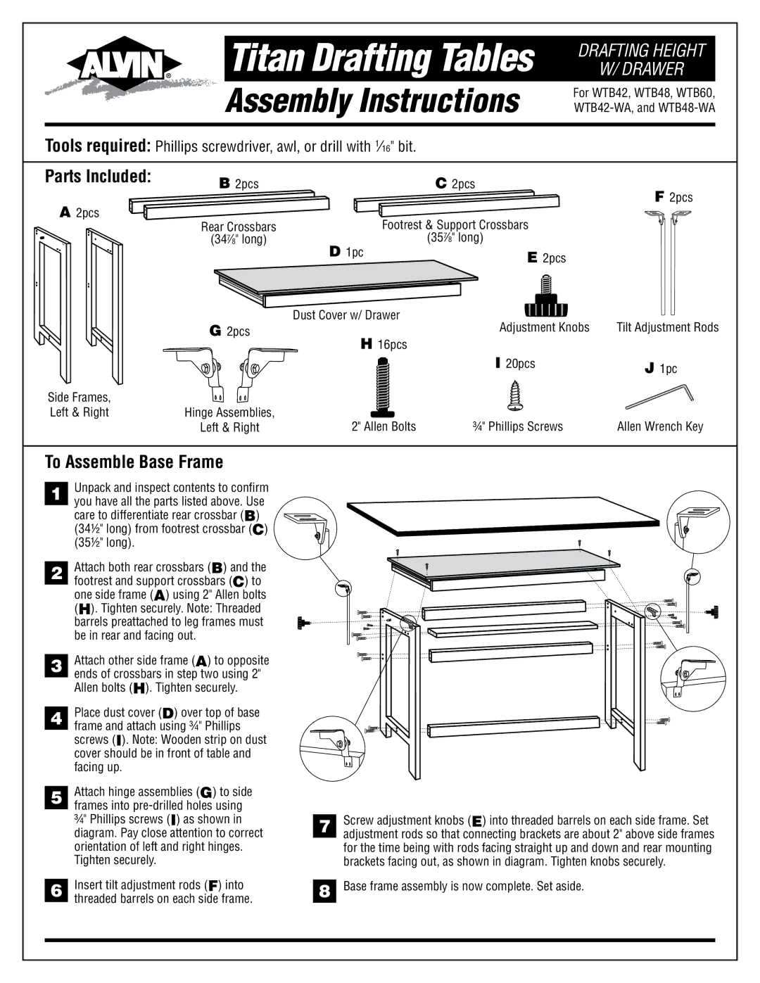
Tools required: Phillips screwdriver, awl, or drill with 1⁄16" bit.
Parts Included: | B 2pcs |
|
| C 2pcs | F 2pcs |
|
|
| |||
A 2pcs |
|
|
|
| |
Rear Crossbars |
| Footrest & Support Crossbars |
| ||
|
|
| |||
| (347⁄8" long) | D | 1pc | (357⁄8" long) |
|
|
| E 2pcs |
| ||
|
|
|
|
| |
| G 2pcs | Dust Cover w/ Drawer | Adjustment Knobs | Tilt Adjustment Rods | |
|
| H 16pcs | |||
|
|
|
|
| |
|
|
|
| I 20pcs | J 1pc |
|
|
|
|
| |
Side Frames, |
|
|
|
|
|
Left & Right | Hinge Assemblies, |
| 2" Allen Bolts | ¾" Phillips Screws | Allen Wrench Key |
| Left & Right |
| |||
To Assemble Base Frame
1 Unpack and inspect contents to confirm you have all the parts listed above. Use care to differentiate rear crossbar (B)
(34½" long) from footrest crossbar (C)
(35½" long).
| Attach both rear crossbars (B) and the | |
2 | ||
footrest and support crossbars (C) to | ||
| one side frame (A) using 2" Allen bolts | |
| (H). Tighten securely. Note: Threaded | |
| barrels preattached to leg frames must | |
| be in rear and facing out. | |
| Attach other side frame (A) to opposite | |
3 | ||
ends of crossbars in step two using 2" | ||
| Allen bolts (H). Tighten securely. | |
| Place dust cover (D) over top of base | |
4 | ||
frame and attach using ¾" Phillips | ||
| screws (I). Note: Wooden strip on dust | |
| cover should be in front of table and | |
| facing up. | |
| Attach hinge assemblies (G) to side | |
5 | ||
frames into | ||
| ¾" Phillips screws (I) as shown in | |
| diagram. Pay close attention to correct | |
| orientation of left and right hinges. | |
| Tighten securely. | |
| Insert tilt adjustment rods (F) into | |
6 | ||
threaded barrels on each side frame. | ||
|
| Screw adjustment knobs (E) into threaded barrels on each side frame. Set | |
7 | ||
adjustment rods so that connecting brackets are about 2" above side frames | ||
| ||
| for the time being with rods facing straight up and down and rear mounting | |
| brackets facing out, as shown in diagram. Tighten knobs securely. | |
| Base frame assembly is now complete. Set aside. | |
8 |