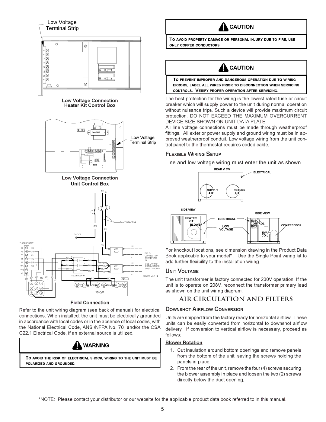
PACKAGE HEAT PUMP specifications
The Amana Package Heat Pump is a versatile and efficient heating and cooling solution designed for residential and commercial applications. Combining both heating and cooling capabilities into one compact unit, the Amana Package Heat Pump provides year-round comfort, making it a popular choice for various climates.One of the main features of the Amana Package Heat Pump is its high energy efficiency. Many models come with a SEER rating of up to 15 or higher, ensuring that users can enjoy effective climate control while minimizing energy costs. The unit’s efficient design helps reduce electricity consumption, which is not only beneficial for the environment but also for homeowners looking to cut down on utility bills.
The Amana Package Heat Pump integrates advanced technologies to optimize performance. One notable feature is its Smart Home integration, enabling users to control their heating and cooling settings remotely through smartphone apps. This feature enhances convenience and allows users to adjust their home’s climate while they are away, ensuring optimal comfort upon their return.
Another key characteristic of this heat pump is its robust construction. The unit is designed to withstand harsh weather conditions, featuring a galvanized steel cabinet that resists corrosion and rust. Some models also come with a weather-resistant outdoor coating, further enhancing durability.
The Amana Package Heat Pump also employs environmentally friendly refrigerants, contributing to a reduced carbon footprint. With a focus on sustainability, the unit is designed to meet or exceed the latest environmental regulations, allowing consumers to make eco-conscious choices.
Furthermore, the heat pump incorporates quiet operation technology, ensuring that it runs at minimal noise levels. This is particularly important in residential settings, where noise can be a significant concern. The unit operates silently, allowing homeowners to enjoy their indoor environment without disturbance.
Installation versatility is another benefit of the Amana Package Heat Pump. Its all-in-one design means that it can be easily installed on rooftops or ground-level pads, making it suitable for a variety of building layouts and space constraints.
In summary, the Amana Package Heat Pump stands out due to its high energy efficiency, advanced technologies, durable construction, eco-friendly refrigerants, quiet operation, and versatile installation options. These features make it an ideal choice for those seeking reliable heating and cooling solutions for their homes or businesses. Whether facing the heat of summer or the chill of winter, the Amana Package Heat Pump ensures comfort throughout the year.

