Manuals
/
AMD
/
Computer Equipment
/
Computer Hardware
AMD
user manual
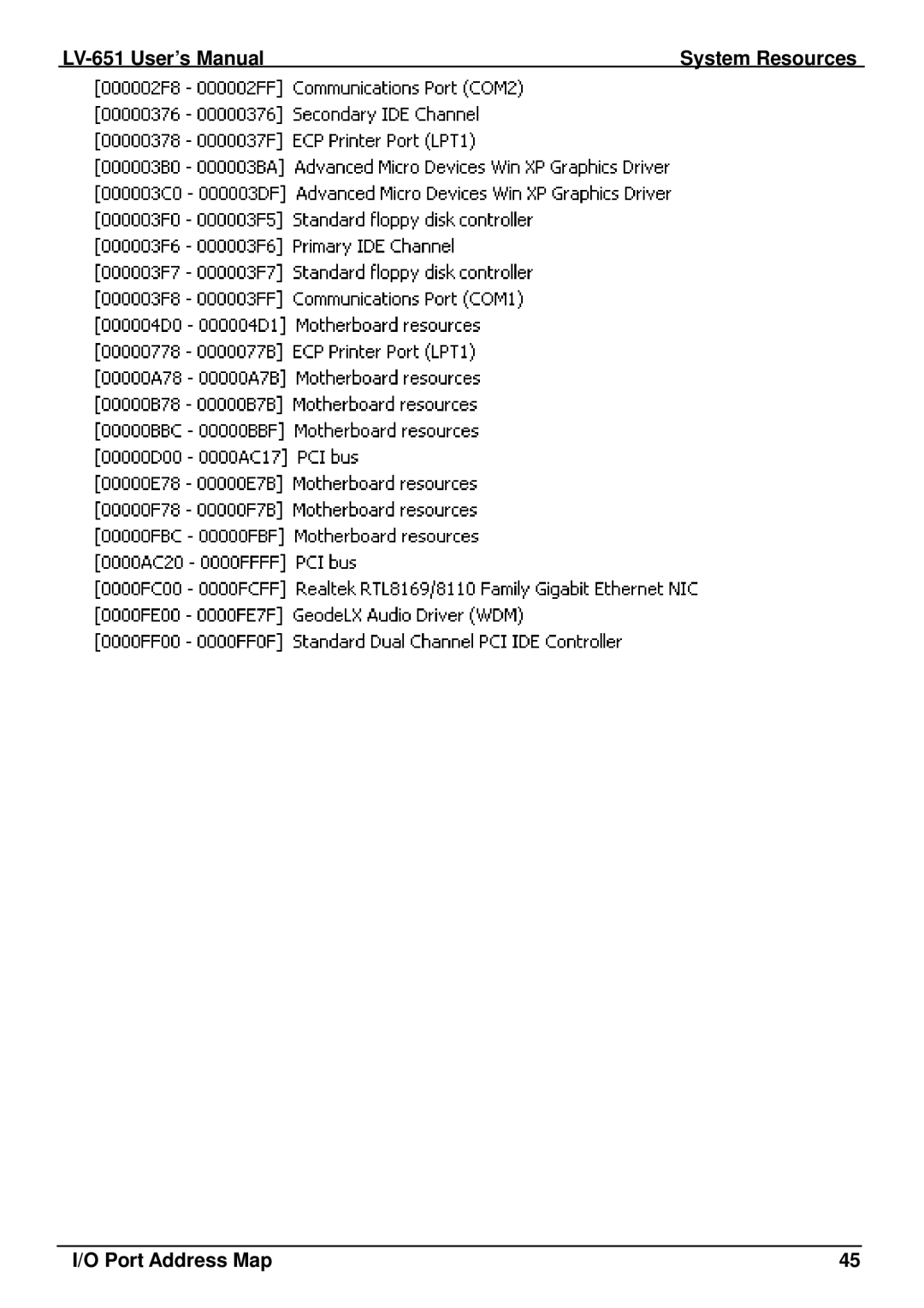
LV-651 User’s Manual System Resources Port Address Map
Models:
LV-651
1
45
50
50
Download
50 pages
33 Kb
42
43
44
45
46
47
48
49
Specification
Install
Block Diagram
Pin Signal
Indicator and Switch
Hardware Setup
Connector Reference
Appendix B Flash Bios
Serial Port Jumper Setting
Resolution
Page 45
Image 45
LV-651
User’s Manual
System Resources
I/O Port Address Map
45
Page 44
Page 46
Page 45
Image 45
Page 44
Page 46
Contents
LV-651
Trademark
Disclaimer
Hardware
Packing List
Cable Kit
Printed Matters
CPU and Memory Setup………………………………………………..15
Chapter <Hardware Setup >………………………………………………………12
Index
Chapter Introduction………………………………………………………………7
Appendix C System Resources…………………………………………….….45
Appendix B Flash BIOS…………………………………………………………43
Is Left For Blank
Product Overview
Introduction
Multi-I/O Port
Product Specification
VGA Display Interface
Ethernet Interface
Audio Interface
Power and Environment
Expansive Interface
Ordering Code
Mechanical Drawing
TFT/LVDS LCD
Block Diagram
Connector Location
Hardware Setup
Jumper Function
Jumper Reference
Connector Reference
Internal Connector
External Connector
CPU and Memory Setup
CPU Setup
Memory Setup
Jrtc Mode
Cmos Setup
Enhanced IDE & CF Interface
Floppy Port
LAN Interface
Onboard Display Interface
Analog VGA Interface
Pin Description
Digital Display
Bit single
Pin Signal 18-bit Signal 24-bit
TCLK1 TCLK1+
Pin Signal
Preparing the LV-651,LCD panel and the backlight inverter
LCD Installation Guide
Panel Number Resolution
Onboard Audio Interface
Interface USB2.0
11 USB2.0 Interface
VCC
Gpio Interface
Serial Port Jumper Setting
JCSEL1 JCSEL2
Power Input
Power and Fan Connector
Power Output
PIN assignment
Fan Connector
PIN
Indicator and Switch
This Page is Left For Blank
1CMOS Setup Utility Main Screen
Bios Setup
This Page is Left for Blank
IDE Port
Appendix a I/O Port Pin Assignment
Serial Port
LAN Port
CRT Port
USB Port
Pin Description MI0+ MI1+ MI2+ MI3+
PS/2 Keyboard & Mouse Port
LPT Port
Pin
This Page is Left for Blank
Appendix B Flash Bios
Bios Auto Flash Tool
Flash Method
C1.I/O Port Address Map
Appendix C System Resources
LV-651 User’s Manual System Resources Port Address Map
C2.Memory Address Map
C3.System IRQ Resources
Program Sample
Appendix D Watch Dog timer Setting
This Page is Left for Blank
Contact Information
Top
Page
Image
Contents