Manuals
/
AMD
/
Computer Equipment
/
Computer Hardware
AMD
NX800LX
user manual
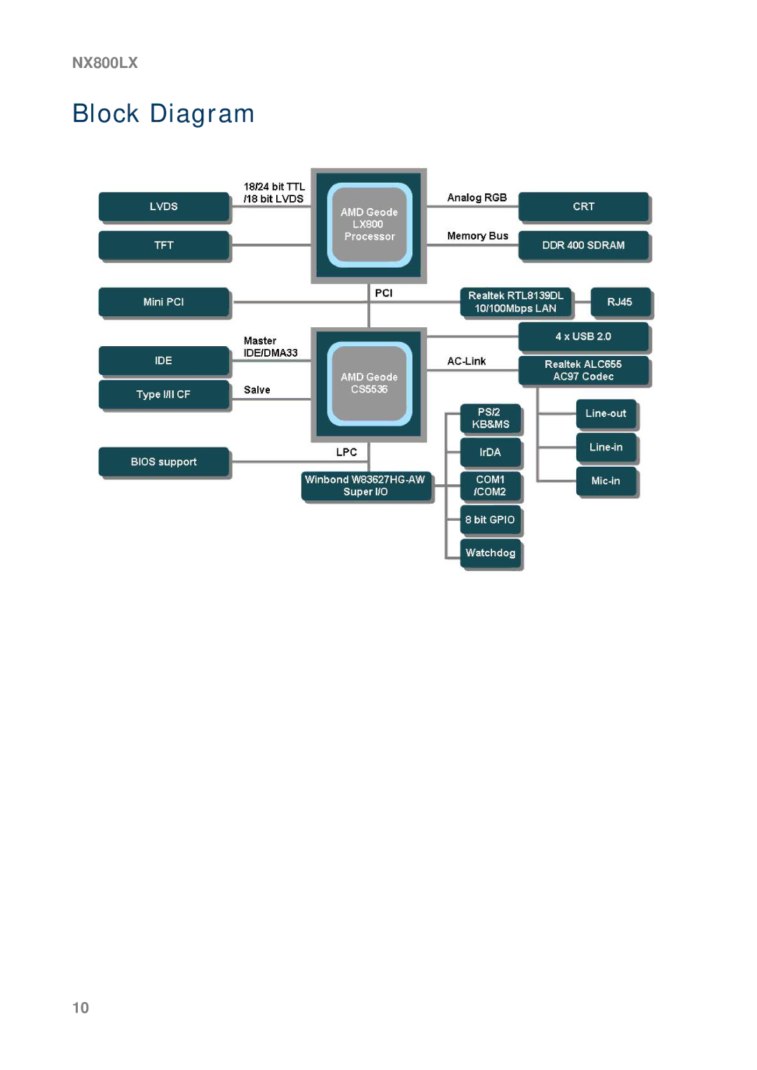
Block Diagram
Models:
NX800LX
1
10
27
27
Download
27 pages
45.23 Kb
7
8
9
10
11
12
13
14
Specs
Install
Block Diagram
Reset Button 2-pin Reset
Internal Connector
Placement Direction
Safety
Power Fan Connector CN7
Page 10
Image 10
NX800LX
Block Diagram
10
Page 9
Page 11
Page 10
Image 10
Page 9
Page 11
Contents
NX800LX
Ver
Contents
User’s Manual
Safety Information
Electrical safety
Technical Support
Conventions Used in This Guide
Packing List
Revision History
Specifications Summary
Features
LAN1
Block Diagram
Product1 Introduction
Production Introduction
Before you Proceed
Motherboard Overview
Placement Direction
Screw Holes
Motherboard Layout
Layout Content List
Label Function
Internal Connector
Configuring an Expansion Card
Installing an Expansion Card
Expansion Slots
Jumpers
Clear Cmos J3
3 COM1/COM2 RI/+5V Selection COMAJ1, COMBJ1
LCD Backlight Brightness Adjustment Connector LCDPJ1
4 COM1/COM2 +5V/+12V Selection COMAPJ1, COMBPJ1
Connectors
Rear Panel Connectors
CF Power Connector CFPJ1 ATX Power Connector CN5
Power Fan Connector CN7
NX800LX
ATX Power Button/Soft-off Button 2-pin Pwrsw
Front Panel Connector FPANEL1
System Power LED 2-pin Pwrled
Reset Button 2-pin Reset
IrDA Connector IRB1 Signal Description
Primary IDE Connector IDEB1
11 AC97 Line-in Connector J1 Gpio Connector J2
LCD Inverter Connector LCDB1
Lvds Connector LVDS1
TTL Connector TTL1 USB 2.0 Connector USBB1
Top
Page
Image
Contents