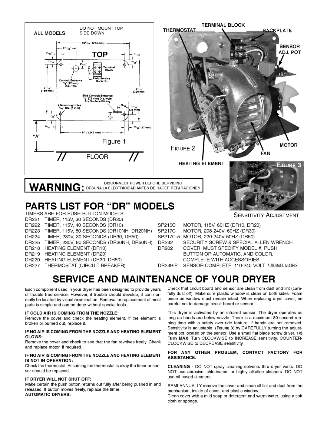
ALL MODELS | DO NOT MOUNT TOP |
SIDE DOWN | |
“A” | Figure 1 |
| |
| FLOOR |
|
|
|
|
THERMOSTAT | TERMINAL BLOCK | BACKPLATE | |
| |||
|
|
|
|
|
|
| SENSOR |
|
|
| ADJ. POT |
|
|
|
|
|
Figure 2 |
|
| MOTOR | |
|
|
|
| |
| FAN |
|
|
|
HEATING ELEMENT |
| Figure 3 | ||
WARNING: DISCONNECT POWER BEFORE SERVICING DESUNA LA ELECTRICIDAD ANTES DE HACER REPARACIONES
-+
PARTS LIST FOR “DR” MODELS | Sensitivity Adjustment | |||
TIMERS ARE FOR PUSH BUTTON MODELS |
| |||
DR221 TIMER, 115V, 30 | SECONDS (DR20) | SP216C | MOTOR, 115V, 60HZ (DR10, DR20) | |
DR222 | TIMER, 115V, 40 | SECONDS (DR10) | ||
DR223 | TIMER, 115V, 80 | SECONDS (DR10NH, DR20NH) | SP217C | MOTOR, |
DR224 | TIMER, 230V, 30 SECONDS (DR30, DR50) | MOTOR, | ||
DR225 | Timer, 230V, 80 Seconds (DR30NH, DR50NH) | DR232 | SECURITY SCREW & SPECIAL ALLEN WRENCH | |
DR218 | HEATING ELEMENT (DR10) | DR202 | COVER, MUST SPECIFY MODEL #, PUSH | |
DR219 | HEATING ELEMENT (DR20) |
| BUTTON OR AUTOMATIC, AND COLOR. | |
DR220 HEATING ELEMENT (DR30, DR50) | COMPLETE WITH ACCESSORIES. | |||
DR227 | THERMOSTAT (CIRCUIT BREAKER) | SENSOR COMPLETE, | ||
SERVICE AND MAINTENANCE OF YOUR DRYER
Each component used in your dryer has been designed to provide years of trouble free service. However, if trouble should develop, it can nor- mally be located by visual examination. Removal or replacement of most parts is simple and can be done without special tools.
IF COLD AIR IS COMING FROM THE NOZZLE:
Remove the cover and check the heating element. If the element is broken or burned out, replace it.
IF NO AIR IS COMING FROM THE NOZZLE AND HEATING ELEMENT GLOWS:
Remove the cover and check to see that the fan revolves freely. Check and replace motor, if required.
IF NO AIR IS COMING FROM THE NOZZLE AND HEATING ELEMENT IS NOT IN OPERATION:
Check the thermostat. Assuming the thermostat is okay the timer or sen- sor should be replaced.
IF DRYER WILL NOT SHUT OFF:
Make certain the push button returns out fully after being pushed in and released. If button moves freely, replace the timer.
AUTOMATIC DRYERS:
Check that circuit board and sensor are clean from dust and lint (care- fully dust off). Make sure plastic window is clean on both sides. Foam piece on window must remain intact. When replacing dryer cover, be careful not to damage circuit board or sensor.
This dryer is activated by an infrared sensor. The dryer operates as long as hands are below nozzle. There is a maximum 80 second run- ning time with a safety
FOR ANY OTHER PROBLEM, CONTACT FACTORY FOR ASSISTANCE.
CLEANING - DO NOT spray cleaning solvents thru dryer vents. DO NOT use abrasive, chlorinated, or highly alkaline cleaners. DO NOT use oil based cleaners.
Clean cover with a mild soap or detergent and warm water, using a soft cloth or sponge.