STACKING KIT(GAS) INSTALLATION INSTRUCTIONS (MAH6700 washer & MDG6700 dryer only)
GAS REQUIREMENTS
Use only Natural or LP (liquid petroleum) gases.
THE INSTALLATION MUST COMFORM WITH LOCAL CODES, OR IN THE ABSENCE OF LOCAL CODES, WITH THE NATIONAL FUEL GAS CODE ANSI/Z223.1, LATEST REVISION (FOR THE UNITED STATES), OR WITH THE
A gas dryer is equipped with a burner orifice for operation on NATURAL gas. If the dryer is to be operated on LP gas, it must be converted for safe and proper performance and must be converted by a qualified service technician.
Gas conversion kits from
Each dryer will provide an input of 22,000 B.T.U. per hour.
A 1/2 inch gas supply line is recommended and must be reduced to connect to the 3/8 inch gas line on the dryer.
The National Fuel Gas Code requires that an accessible, approved manual gas shut off valve be installed within 6 feet of the dryer.
Additionally, a 1/8 inch N.P.T. (National Pipe Thread) plugged tapping, accessible for test gauge connection, must be installed immediately upstream of the gas supply connection to the dryer.
The dryer must be disconnected from the gas supply piping system during any pressure testing of the system.
The Flexing Gas Connector supplied with this kit must be uesd for this installation. In all applications with the dryer stacked on a washer, the Maytag Flexing Gas Line Connector(p/n34001465)must be used.
Failure to comply may result in gas line failure or gas leaks.
NOTE : Any pipe joint compound used must be resistant to the action of any liquified petroleum gas.
GAS IGNITION- The dryer uses an automatic ignition system to ignite the burner.
There is no constant burning pilot.
Caution : Two people are required to lift the dryer on to the washer.
Dryer
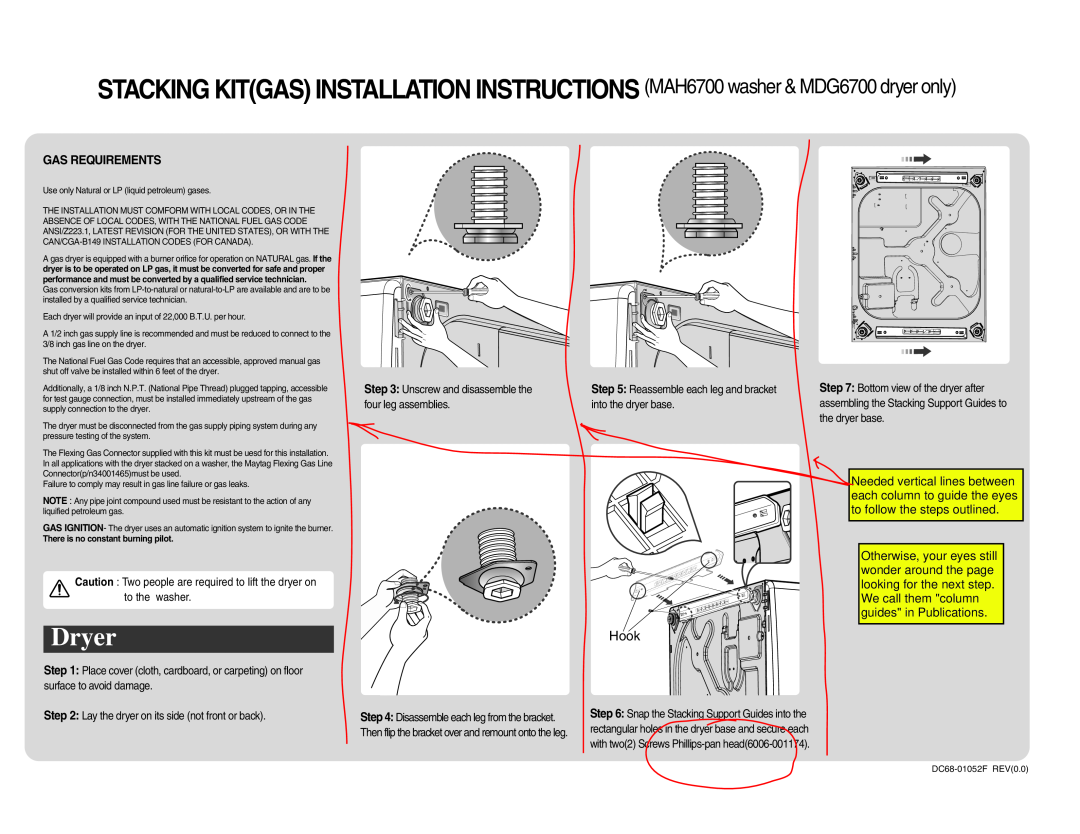
Step 1: Place cover (cloth, cardboard, or carpeting) on floor surface to avoid damage.
Step 2: Lay the dryer on its side (not front or back).
Step 3: Unscrew and disassemble the | Step 5: Reassemble each leg and bracket | Step 7: Bottom view of the dryer after | |||
four leg assemblies. | into the dryer base. | assembling the Stacking Support Guides to | |||
|
| the dryer base. | |||
|
|
|
|
|
|
|
|
|
|
|
|
|
|
|
|
|
|
|
|
|
|
|
|
Hook
Step 4: Disassemble each leg from the bracket. | Step 6: Snap the Stacking Support Guides into the | |
Then flip the bracket over and remount onto the leg. | rectangular holes in the dryer base and secure each | |
with two(2) Screws | ||
|
Ne ea to
Ot wo loo
W gu
