®
1CONTENTS
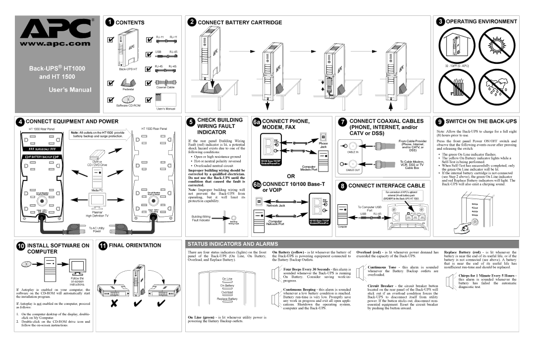
2 | CONNECT BATTERY CARTRIDGE | 3 OPERATING ENVIRONMENT |
www.apc.com
Back-UPS® HT1000
and HT 1500
User’s Manual
✔ ![]()
![]()
✔
Pedestal
✔
Software
✔
✔USB
✔
✔![]()
![]()
![]()
![]()
![]()
![]()
![]()
Coaxial Cable
®
✔
User’s Manual
32 - 104oF (0 - 40oC) |
4 CONNECT EQUIPMENT AND POWER |
| 5 | CHECK BUILDING | 6a CONNECT PHONE, |
| 7 | CONNECT COAXIAL CABLES | ||||
HT 1000 Rear Panel |
| HT 1500 Rear Panel |
| WIRING FAULT |
| MODEM, FAX |
|
| (PHONE, INTERNET, and/or | ||
| Note: All outlets on the HT1500 provide |
|
| INDICATOR |
|
|
|
| CATV or DSS) | ||
| battery backup and surge protection. |
| If | the rear panel | Building Wiring | Outlet |
|
|
| From Cable Provider | |
|
|
|
|
|
| ||||||
|
|
|
|
|
|
| Wall | Phone |
|
|
|
|
|
| Fault (red) indicator is lit, a potential |
|
|
| (Phone, Internet, | ||||
SURGEONLY |
|
| shock hazard exists due to one of the |
| Jack |
|
| and/or CATV, or | |||
|
| following conditions: |
|
|
|
| CABLE IN | DSS) | |||
|
|
|
|
|
|
|
| ||||
BATTERY BACKUP |
|
| • | Open or high resistance ground |
|
|
|
|
| ||
| DVR or |
| • | Hot or neutral polarity reversed | 10/100 |
|
|
| To Cable Modem, | ||
| CD / DVD Drive |
| • | Overloaded neutral circuit |
| Modem/Phone/Fax |
|
|
| VCR, DSS or TV | |
|
|
| Computer |
|
|
| |||||
|
|
| Improper building wiring should be | Modem Port |
|
| CABLE OUT | Cable Box | |||
|
|
| corrected by a qualified electrician. | OR |
|
|
|
| |||
|
|
| Do not use the |
|
|
|
| ||||
|
|
| condition that caused the fault is | 6b CONNECT 10/100 | 8 | CONNECT INTERFACE CABLE | |||||
|
|
| corrected. |
|
| ||||||
Circuit Breaker | Media PC | Circuit Breaker | Note: Improper building wiring will | or VOIP |
|
|
| For connection of APC’s optional | |||
Push to Reset |
| Push to Reset | not | prevent the | from |
|
|
|
| external | |
|
|
| operating, but it | will limit | its |
|
|
|
| ||
|
|
|
| Wall |
|
| (BR24BP) to the | ||||
|
|
| protection capability. |
|
|
|
| ||||
|
|
|
|
| Outlet |
|
|
| |||
|
|
|
| Network Jack | To Computer USB |
|
| |
|
|
|
|
|
|
| ||
Input: 120V~ | Plasma/ | Input: 120V~ |
|
|
| Port |
|
|
12A, 60Hz | 12A, 60Hz |
|
| USB | Data Port | BR24BP Battery Pack | ||
| High Definition TV | Building Wiring |
|
|
|
| ||
|
|
|
|
|
|
| ||
|
| Fault Indicator | Building | Computer | 10/100 |
|
|
|
|
|
| Modem/Phone/Fax |
|
|
| ||
|
|
| Wiring Fault | Network Port |
|
|
| |
| To AC Utility |
|
|
| Computer |
|
|
|
|
|
|
|
|
|
|
| |
| Power |
|
|
|
|
|
|
|
9SWITCH ON THE BACK-UPS
Note: Allow the
(8) hours prior to use.
Press the front panel Power ON/OFF switch and observe that the following events occur after pressing and releasing the switch:
•The green On Line indicator flashes.
•The yellow On Battery indicator lights while a
•When
•If the internal battery cartridge is not connected (see Step 2 above), the green On Line indicator and red Replace Battery indicators will light. The
10 INSTALL SOFTWARE ON |
11 FINAL ORIENTATION |
STATUS INDICATORS AND ALARMS
COMPUTER |
Follow the
If Autoplay is enabled on your computer, the software on the
If Autoplay is not enabled on the computer, proceed as follows:
1.On the computer desktop of the display, double- click on My Computer.
2.
✘ ✔ ✔ |
There are four status indicators (lights) on the front panel of the
On Line
On Battery
Overload
Replace Battery
On Line (green) - is lit whenever utility power is powering the Battery Backup outlets.
On Battery (yellow) - is lit whenever the battery of the
![]()
![]() Four Beeps Every 30 Seconds - this alarm is sounded whenever the
Four Beeps Every 30 Seconds - this alarm is sounded whenever the ![]()
![]() progress.
progress.
Continuous Beeping - this alarm is sounded ![]()
![]() whenever a low battery condition is reached.
whenever a low battery condition is reached.
Battery ![]() cations. Shutdown the operating system,
cations. Shutdown the operating system,
![]() computer and the
computer and the
Overload (red) - is lit whenever power demand has exceeded the capacity of the
![]()
![]() Continuous Tone - this alarm is sounded whenever the Battery Backup outlets are overloaded.
Continuous Tone - this alarm is sounded whenever the Battery Backup outlets are overloaded.
Circuit Breaker - the circuit breaker button located on the rear panel of the
Replace Battery (red) - is lit whenever the battery is near the end of its useful life, or if the battery is not connected (see above). A battery that is near the end of its useful life has insufficient
![]()
![]() Chirps for 1 Minute Every 5 Hours - this alarm is sounded whenever the battery has failed the automatic
Chirps for 1 Minute Every 5 Hours - this alarm is sounded whenever the battery has failed the automatic ![]() diagnostic test.
diagnostic test.