American Power Conversion XS 450 -48 user manual Rectifier Shelf Serial Communications

Models: XS 450 -48

1 48
Download 48 pages 21.3 Kb
Page 17
Image 17

Rectifier Shelf Serial Communications

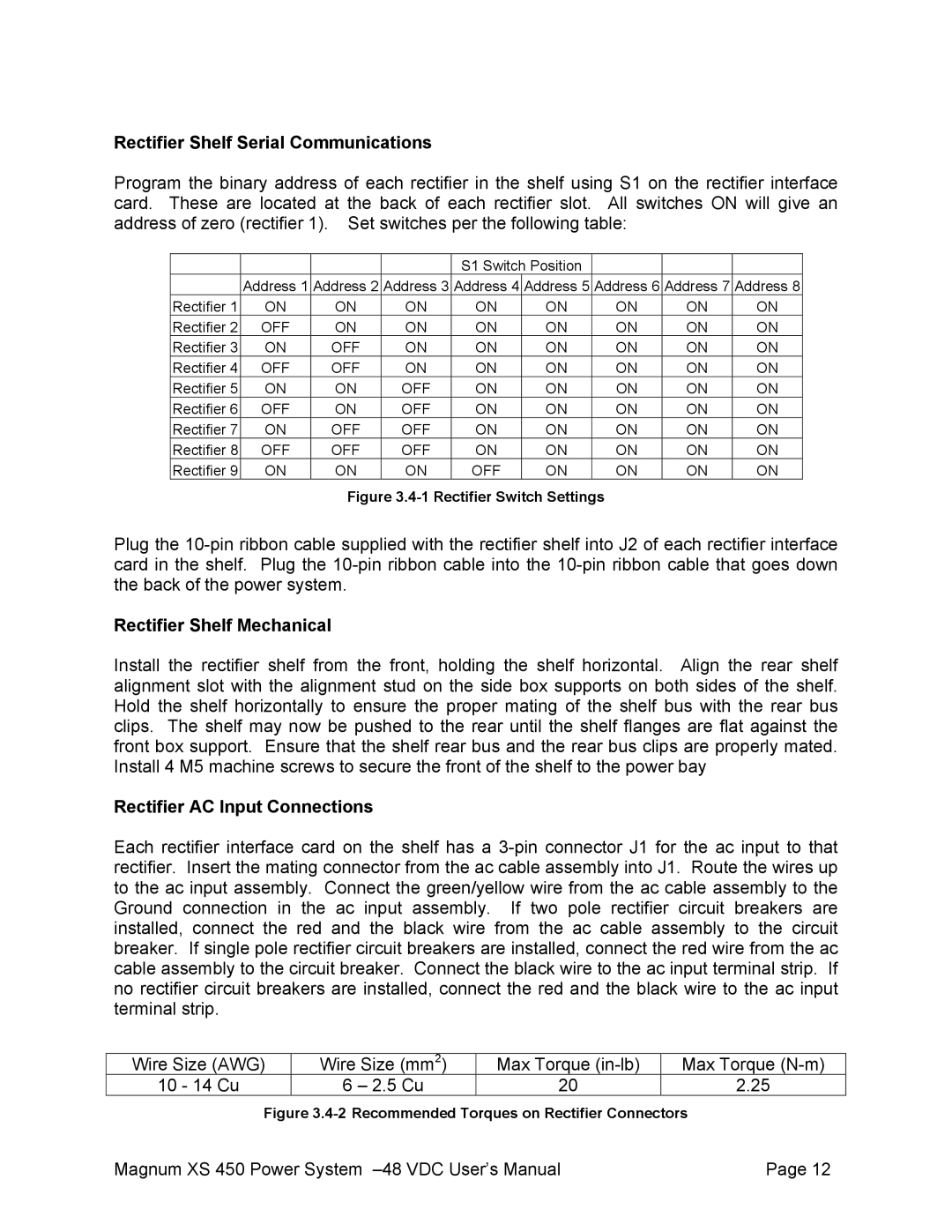
Program the binary address of each rectifier in the shelf using S1 on the rectifier interface card. These are located at the back of each rectifier slot. All switches ON will give an address of zero (rectifier 1). Set switches per the following table:


S1 Switch Position


Address 1

Address 2

Address 3

Address 4

Address 5

Address 6

Address 7

Address 8

Rectifier 1

ON

ON

ON

ON

ON

ON

ON

ON

Rectifier 2

OFF

ON

ON

ON

ON

ON

ON

ON

Rectifier 3

ON

OFF

ON

ON

ON

ON

ON

ON

Rectifier 4

OFF

OFF

ON

ON

ON

ON

ON

ON

Rectifier 5

ON

ON

OFF

ON

ON

ON

ON

ON

Rectifier 6

OFF

ON

OFF

ON

ON

ON

ON

ON

Rectifier 7

ON

OFF

OFF

ON

ON

ON

ON

ON

Rectifier 8

OFF

OFF

OFF

ON

ON

ON

ON

ON

Rectifier 9

ON

ON

ON

OFF

ON

ON

ON

ON

Figure 3.4-1 Rectifier Switch Settings

Plug the 10-pin ribbon cable supplied with the rectifier shelf into J2 of each rectifier interface card in the shelf. Plug the 10-pin ribbon cable into the 10-pin ribbon cable that goes down the back of the power system.

Rectifier Shelf Mechanical

Install the rectifier shelf from the front, holding the shelf horizontal. Align the rear shelf alignment slot with the alignment stud on the side box supports on both sides of the shelf. Hold the shelf horizontally to ensure the proper mating of the shelf bus with the rear bus clips. The shelf may now be pushed to the rear until the shelf flanges are flat against the front box support. Ensure that the shelf rear bus and the rear bus clips are properly mated. Install 4 M5 machine screws to secure the front of the shelf to the power bay

Rectifier AC Input Connections

Each rectifier interface card on the shelf has a 3-pin connector J1 for the ac input to that rectifier. Insert the mating connector from the ac cable assembly into J1. Route the wires up to the ac input assembly. Connect the green/yellow wire from the ac cable assembly to the Ground connection in the ac input assembly. If two pole rectifier circuit breakers are installed, connect the red and the black wire from the ac cable assembly to the circuit breaker. If single pole rectifier circuit breakers are installed, connect the red wire from the ac cable assembly to the circuit breaker. Connect the black wire to the ac input terminal strip. If no rectifier circuit breakers are installed, connect the red and the black wire to the ac input terminal strip.


Wire Size (AWG)

Wire Size (mm2)

Max Torque (in-lb)

Max Torque (N-m)

10 - 14 Cu

6 – 2.5 Cu

20

2.25

Figure 3.4-2 Recommended Torques on Rectifier Connectors

Magnum XS 450 Power System –48 VDC User’s Manual

Page 12

Page 17
Image 17
American Power Conversion XS 450 -48 user manual Rectifier Shelf Serial Communications, Rectifier Shelf Mechanical

XS 450 -48 specifications

The American Power Conversion (APC) XS 450 -48 is a reliable and efficient power supply solution designed for critical applications requiring a consistent and stable power source. This solution is particularly beneficial for telecommunications, data centers, and industrial settings where power reliability is paramount.

One of the key features of the XS 450 -48 is its ability to deliver 450 watts of continuous power, ensuring that connected devices receive uninterrupted power supply. Its 48-volt output makes it ideal for telecom requirements, where 48V systems are standard. The unit provides a compact and space-saving design, making it suitable for installation in rack-mounted configurations, optimizing the utilization of valuable real estate in server rooms or equipment racks.

The XS 450 -48 utilizes advanced technologies that enhance its performance and reliability. It is equipped with an active power factor correction (PFC) system that significantly reduces harmonic distortion. This feature not only improves system efficiency but also complies with various regulations concerning power quality. Additionally, the power supply includes built-in over-voltage protection, over-current protection, and short-circuit protection, ensuring that both the power supply and the connected devices are safeguarded against electrical faults.

The unit is designed for high efficiency, often exceeding 90% under full load conditions. This not only reduces energy costs but also minimizes heat generation, contributing to a quieter operation environment. The XS 450 -48's intelligent thermal management system allows it to operate in a range of temperatures, making it highly versatile and adaptable to varying environmental conditions.

Furthermore, monitoring and management capabilities are integrated into the XS 450 -48 with optional external monitoring systems. These systems provide critical insights, allowing technicians to track real-time performance metrics, detect potential issues early on, and perform preventive maintenance.

In conclusion, the American Power Conversion XS 450 -48 stands out as a robust power supply solution that combines reliable performance, advanced protection features, and high efficiency. Its design caters to the specific needs of telecommunications and data centers, making it an indispensable asset for maintaining the uptime and integrity of critical systems. With its range of features and reliability, the XS 450 -48 continues to be a preferred choice among professionals in the field.