9 | TANK |
| WATER INLET |
WASHER ![]()
FLEXIBLE
COUPLING NUT ![]()
![]()
![]()
![]()
![]()
![]() SUPPLY
SUPPLY
VALVE NUT
![]() COMPRESSION
COMPRESSION
COLLAR
TRIM PLATE
VALVE
CAUTION: Overtightening of COUPLING NUT could result in breakage and potential flooding.
CONNECT WATER SUPPLY
a.Connect water supply line between shutoff valve and tank water inlet fitting. Tighten COUPLING NUT 1/4 turn beyond hand tight. Check that refill tube is inserted into overflow tube.
b.Turn on supply valve and allow tank to fill until float rises to shutoff position.
c.Check for leakage at fittings, tighten or correct as needed.
d.Do not use plumber's putty to seal these fittings.
10
TO RAISE |
| FLOW RATE |
|
|
| ADJUSTMENT |
| ||
WATER |
|
| LIFT |
|
LEVEL | + | OVERFLOW |
| |
| ROD |
| ||
TO LOWER | TUBE |
| ||
|
| |||
- | REFILL |
|
| |
WATER |
|
|
| |
LEVEL |
| TUBE |
|
|
TRIP |
|
| FLOAT | FIG. 10A |
LEVER | C L |
|
| |
|
| BALL |
| |
|
|
|
| |
WATER CONTROL |
|
|
|
|
ASSEMBLY |
|
|
|
|
WATER LINE |
|
| FLUSH |
|
LEVEL |
|
|
| |
|
| VALVE |
| |
|
|
| FLOAT |
|
WATER INLET |
|
| FLAPPER |
|
|
| ASSEMBLY |
| |
| FLUSH VALVE |
|
| |
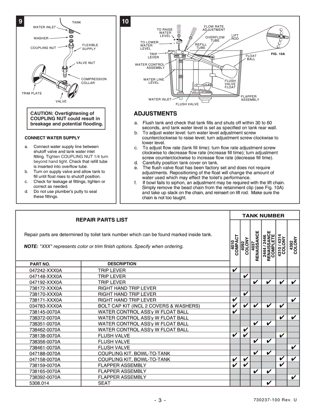
ADJUSTMENTS
a.Flush tank and check that tank fills and shuts off within 30 to 60 seconds, and tank water level is set as specified on tank rear wall.
b.To adjust water level: turn water level adjustment screw counterclockwise to raise level; turn adjustment screw clockwise to lower level.
c.To adjust flow rate (tank fill time): turn flow rate adjustment screw clockwise to decrease flow rate (increase fill time); turn adjustment screw counterclockwise to increase flow rate (decrease fill time).
d.Carefully position tank cover on tank.
e.The flush valve float has been factory set and does not require adjustments. Repositioning of the float will change the amount of water used which may effect the toilet's performance.
f.If bowl fails to siphon, an adjustment may be required with the lift chain. Simply remove the bead chain from the retainment clip (see Fig. 10A) and take up slack on the chain, and reinsert on lift rod. Make sure the chain is not too taught.
| REPAIR PARTS LIST |
| TANK NUMBER |
| |||
| 4010 COMPACT 4092 COLONY 4037 RENAISSANCE | 2446/2444 RENAISSANCE COMPLETE 4314/4310 COLONY | 4392 COLONY | ||||
Repair parts are determined by toilet tank number which can be found marked inside tank. | |||||||
|
|
|
|
| |||
NOTE: "XXX" represents color or trim finish options. Specify when ordering. |
|
|
|
|
| ||
PART NO. | DESCRIPTION |
|
|
|
|
| |
TRIP LEVER | ✔ |
|
|
|
| ||
TRIP LEVER |
| ✔ |
|
|
| ||
TRIP LEVER |
| ✔ | ✔ | ✔ | ✔ | ||
RIGHT HAND TRIP LEVER |
| ✔ |
|
|
| ||
RIGHT HAND TRIP LEVER | ✔ |
|
|
| |||
RIGHT HAND TRIP LEVER |
|
|
| ✔ | |||
BOLT CAP KIT (INCL 2 COVERS & WASHERS) | ✔ | ✔ ✔ | ✔ | ✔ |
| ||
WATER CONTROL ASS'y W FLOAT BALL | ✔ |
|
| ✔ | ✔ | ||
WATER CONTROL ASS'y W FLOAT BALL |
| ✔ | ✔ | ||||
WATER CONTROL ASS'y W FLOAT BALL |
|
|
| ||||
WATER CONTROL ASS'y W FLOAT BALL | ✔ | ✔ |
|
|
| ||
FLUSH VALVE | ✔ |
| ✔ |
| |||
FLUSH VALVE |
| ✔ | ✔ |
|
| ||
FLUSH VALVE |
| ✔ | ✔ |
| ✔ | ||
COUPLING KIT, |
| ✔ | ✔ | ||||
COUPLING KIT, | ✔ | ✔ |
| ||||
FLAPPER ASSEMBLY | ✔ | ✔ |
| ✔ |
| ||
FLAPPER ASSEMBLY |
| ✔ | ✔ |
|
| ||
FLAPPER ASSEMBLY |
|
|
|
| ✔ | ||
5308.014 | SEAT |
|
| ✔ |
|
| |
| - 3 - |
| |||||