INSTALLATION AND FRAMING INSTRUCTIONS
The variety of installations possible for this whirlpool may require framing procedures other than those shown. Locate studs as required. Ensure
NOTE: The apron should not be used as the primary access opening.
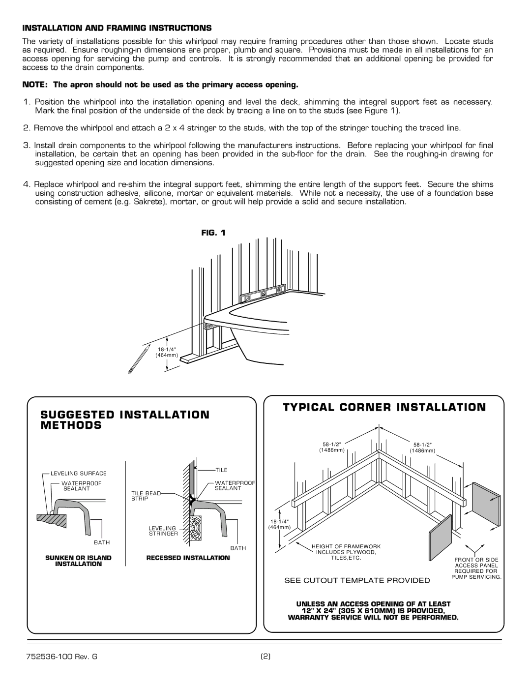
1.Position the whirlpool into the installation opening and level the deck, shimming the integral support feet as necessary. Mark the final position of the underside of the deck by tracing a line on to the studs (see Figure 1).
2.Remove the whirlpool and attach a 2 x 4 stringer to the studs, with the top of the stringer touching the traced line.
3.Install drain components to the whirlpool following the manufacturers instructions. Before replacing your whirlpool for final installation, be certain that an opening has been provided in the
4.Replace whirlpool and
FIG. 1
(464mm)
SUGGESTED INSTALLATION METHODS
TYPICAL CORNER INSTALLATION
LEVELING SURFACE
WATERPROOF
SEALANT
BATH
SUNKEN OR ISLAND
INSTALLATION
(1486mm) | (1486mm) |
TILE
WATERPROOF
SEALANT
TILE BEAD
STRIP
|
| |
LEVELING | (464mm) |
|
STRINGER |
|
|
BATH | HEIGHT OF FRAMEWORK |
|
RECESSED INSTALLATION | INCLUDES PLYWOOD, |
|
TILES,ETC. | FRONT OR SIDE | |
|
| ACCESS PANEL |
|
| REQUIRED FOR |
| SEE CUTOUT TEMPLATE PROVIDED | PUMP SERVICING. |
|
|
UNLESS AN ACCESS OPENING OF AT LEAST 12" X 24" (305 X 610MM) IS PROVIDED, WARRANTY SERVICE WILL NOT BE PERFORMED.
(2) |