1a | INSTALL FAUCET WITHOUT ESCUTCHEON PLATE |
(4101.115 with soap dish) (4101.350 less soap dish) |
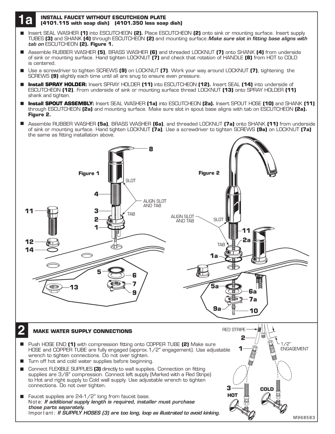
Insert SEAL WASHER (1) into ESCUTCHEON (2). Place ESCUTCHEON (2) onto sink or mounting surface. Insert supply TUBES (3) and SHANK (4) through ESCUTCHEON (2) and mounting surface.Make sure slot in fitting base aligns with tab on ESCUTCHEON (2). Figure 1.
Assemble RUBBER WASHER (5), BRASS WASHER (6) and threaded LOCKNUT (7) onto SHANK (4) from underside of sink or mounting surface. Hand tighten LOCKNUT (7) and check that rotation of HANDLE (8) from HOT to COLD is centered.
Use a screwdriver to tighten SCREWS (9) on LOCKNUT (7). Work your way around LOCKNUT (7), tightening the SCREWS (9) slightly each time until all are snug to ensure even pressure.
Install SPRAY HOLDER: Insert SPRAY HOLDER (11) into ESCUTCHEON (12). Insert SEAL (14) into underside of ESCUTCHEON (12). From underside of sink or mounting surface thread LOCKNUT (13) onto SPRAY HOLDER (11) shank and tighten.
Install SPOUT ASSEMBLY: Insert SEAL WASHER (1a) into ESCUTCHEON (2a). Insert SPOUT HOSE (10) and SHANK (11) through ESCUTCHEON (2a) and mounting surface. Make sure slot in spout base aligns with tab on ESCUTCHEON (2a).
Figure 2.
Assemble RUBBER WASHER (5a), BRASS WASHER (6a), and threaded LOCKNUT (7a) onto SHANK (11) from underside of sink or mounting surface. Hand tighten LOCKNUT (7a). Use a screwdriver to tighten SCREWS (9a) on LOCKNUT (7a) the same as fitting installation above.
8
Figure 1 | Figure 2 |
SLOT
4
11 | 3 |
| 2 |
| 1 |
ALIGN SLOT
AND TAB
TAB | ALIGN SLOT |
|
| SLOT | |
| AND TAB | |
|
|
11 ![]()
12 |
|
| 2a | |
14 |
| TAB | ||
| 1a |
| ||
|
|
| ||
5 | 6 |
|
| |
|
|
| ||
13 | 7 | 5a |
| |
9 | 6a | |||
|
| |||
|
|
| 7a | |
|
| 9a | 10 | |
|
|
| ||
2 MAKE WATER SUPPLY CONNECTIONS |
|
| RED STRIPE | |
|
|
| ||
2
Push HOSE END (1) with compression fitting onto COPPER TUBE (2) Make sure
HOSE and COPPER TUBE are fully engaged (approx.1/2" engagement). Use adjustable 1 wrench to tighten connections. Do not over tighten.
Turn off hot and cold water supplies before beginning.
1/2"
ENGAGEMENT
Connect FLEXIBLE SUPPLIES (3) directly to wall supplies. Connection on fitting supplies are 3/8" compression. Connect left supply (Marked with a Red Stripe) to Hot and right supply to Cold wall supply. Use adjustable wrench to tighten connections. Do not over tighten.
Faucet supplies are
Note: If additional supply length is required, installer must purchase those parts separately.
Important: If SUPPLY HOSES (3) are too long, loop as illustrated to avoid kinking.
3COLD 
HOT 
M 9 6 8 5 8 3