10HOWTO SET DETECTION RANGE (If Required) ; Fig. 13 & 14
Note: The detection distance is preset and is ideal for most installations. Should an adjustment be required follow the steps below.
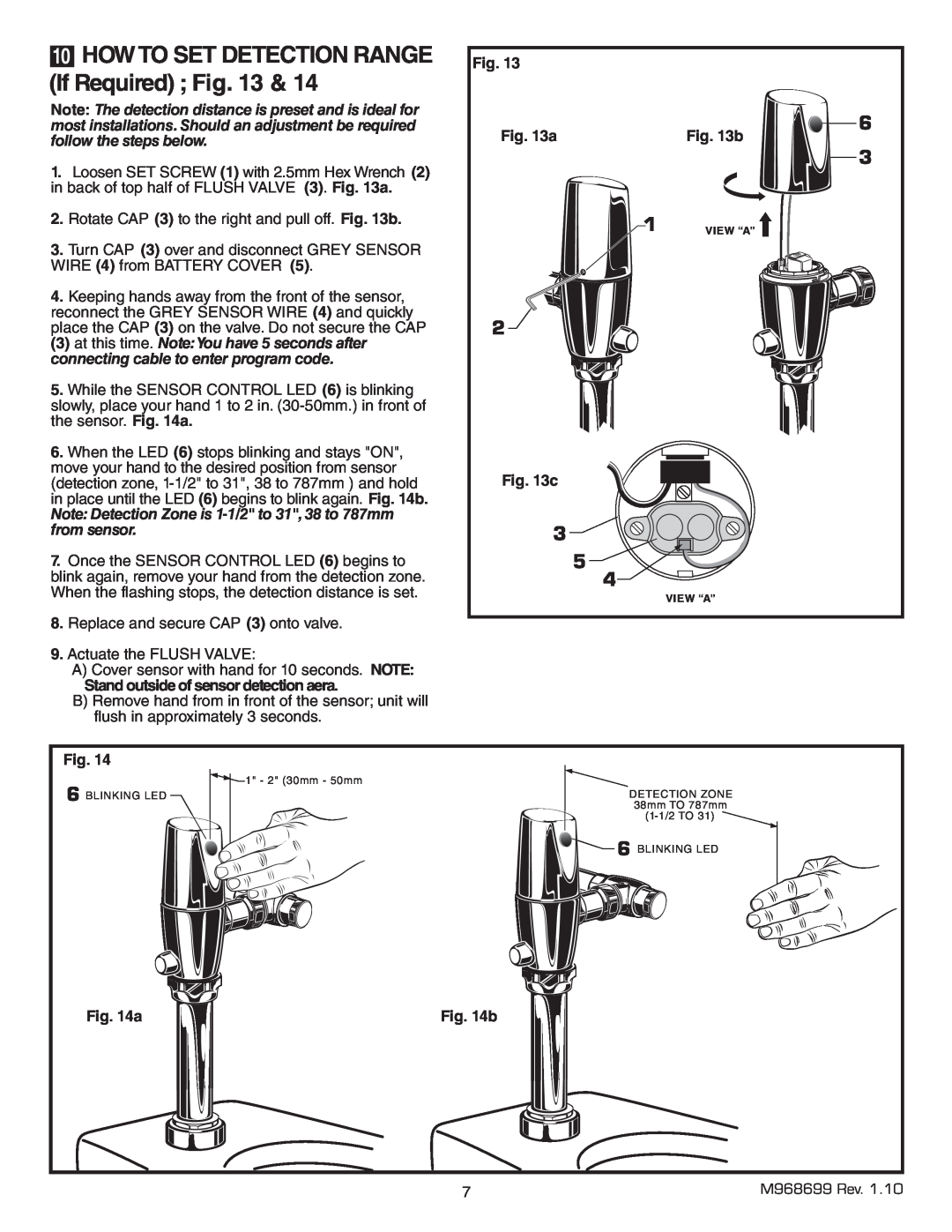
1.Loosen SET SCREW (1) with 2.5mm Hex Wrench (2) in back of top half of FLUSH VALVE (3). Fig. 13a.
2.Rotate CAP (3) to the right and pull off. Fig. 13b.
3.Turn CAP (3) over and disconnect GREY SENSOR WIRE (4) from BATTERY COVER (5).
4.Keeping hands away from the front of the sensor, reconnect the GREY SENSOR WIRE (4) and quickly place the CAP (3) on the valve. Do not secure the CAP
(3) at this time. Note:You have 5 seconds after connecting cable to enter program code.
5.While the SENSOR CONTROL LED (6) is blinking slowly, place your hand 1 to 2 in.
6.When the LED (6) stops blinking and stays "ON", move your hand to the desired position from sensor (detection zone,
Note: Detection Zone is
7.Once the SENSOR CONTROL LED (6) begins to blink again, remove your hand from the detection zone. When the flashing stops, the detection distance is set.
8.Replace and secure CAP (3) onto valve.
9.Actuate the FLUSH VALVE:
A)Cover sensor with hand for 10 seconds. NOTE:
Stand outside of sensor detection aera.
B)Remove hand from in front of the sensor; unit will flush in approximately 3 seconds.
Fig. 13 |
|
Fig. 13a | 6 |
Fig. 13b | |
| 3 |
1 | VIEW “A” |
2 |
|
Fig. 13c |
|
3 |
|
5 |
|
4 |
|
| VIEW “A” |
Fig. 14
6 BLINKING LED
![]() 1" - 2" (30mm - 50mm
1" - 2" (30mm - 50mm
DETECTION ZONE
38mm TO 787mm
![]() 6 BLINKING LED
6 BLINKING LED
Fig. 14a | Fig. 14b |
7 | M968699 Rev. 1.10 |