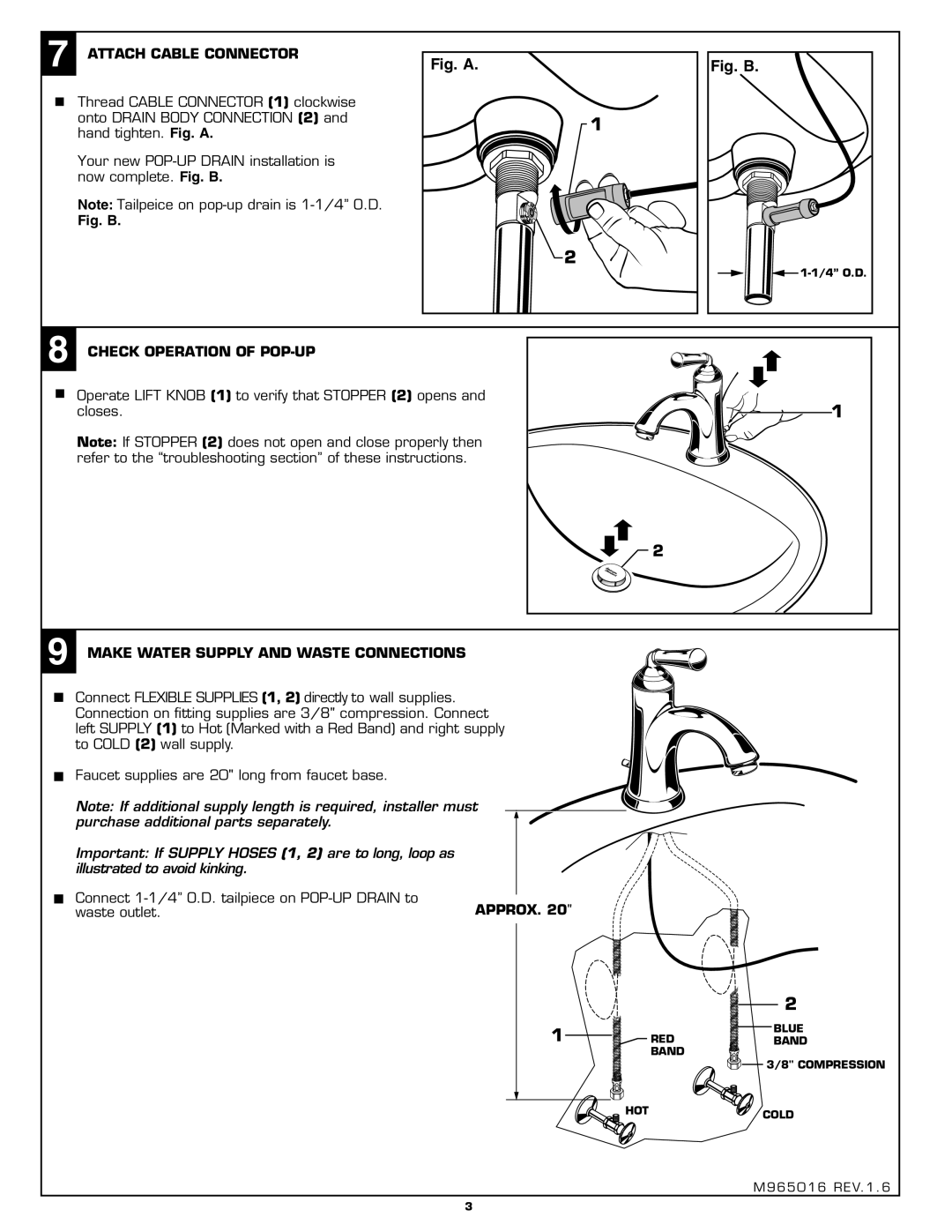
7 | ATTACH CABLE CONNECTOR |
|
|
|
|
| ||
Fig. A. |
|
| Fig. B. | |||||
|
|
| Thread CABLE CONNECTOR (1) clockwise |
|
|
|
|
|
|
|
|
|
|
|
| ||
|
|
|
|
|
|
| ||
|
|
| onto DRAIN BODY CONNECTION (2) and |
| 1 |
|
|
|
|
|
| hand tighten. Fig. A. |
|
|
|
| |
|
|
|
|
|
|
|
| |
Your new
Note: Tailpeice on
Fig. B.
|
|
|
|
| 2 |
|
|
|
|
| ||
|
|
|
|
|
|
|
|
|
|
| ||
|
|
|
|
|
|
|
|
|
|
| ||
|
|
|
|
|
|
|
|
|
|
| ||
|
|
|
|
|
|
|
|
|
|
|
|
|
8 | CHECK OPERATION OF |
|
|
|
|
|
|
|
| |||
|
|
|
|
|
|
|
| |||||
|
|
| Operate LIFT KNOB (1) to verify that STOPPER (2) opens and | 1 |
| |||||||
|
|
| ||||||||||
|
|
| ||||||||||
|
|
| closes. |
| ||||||||
|
|
| Note: If STOPPER (2) does not open and close properly then |
|
|
|
|
|
|
|
| |
|
|
| refer to the “troubleshooting section” of these instructions. |
|
|
|
|
|
|
|
| |
![]() 2
2
9 MAKE WATER SUPPLY AND WASTE CONNECTIONS
Connect FLEXIBLE SUPPLIES (1, 2) directly to wall supplies. Connection on fitting supplies are 3/8" compression. Connect left SUPPLY (1) to Hot (Marked with a Red Band) and right supply to COLD (2) wall supply.
Faucet supplies are 20" long from faucet base.
Note: If additional supply length is required, installer must purchase additional parts separately.
Important: If SUPPLY HOSES (1, 2) are to long, loop as |
|
illustrated to avoid kinking. |
|
Connect | APPROX. 20" |
waste outlet. |
1
2
BLUE
REDBAND BAND
3/8" COMPRESSION
![]() HOT
HOT![]() COLD
COLD
M965016 REV.1.6
3