2
1)Move console table legs into approximate position near the wall.
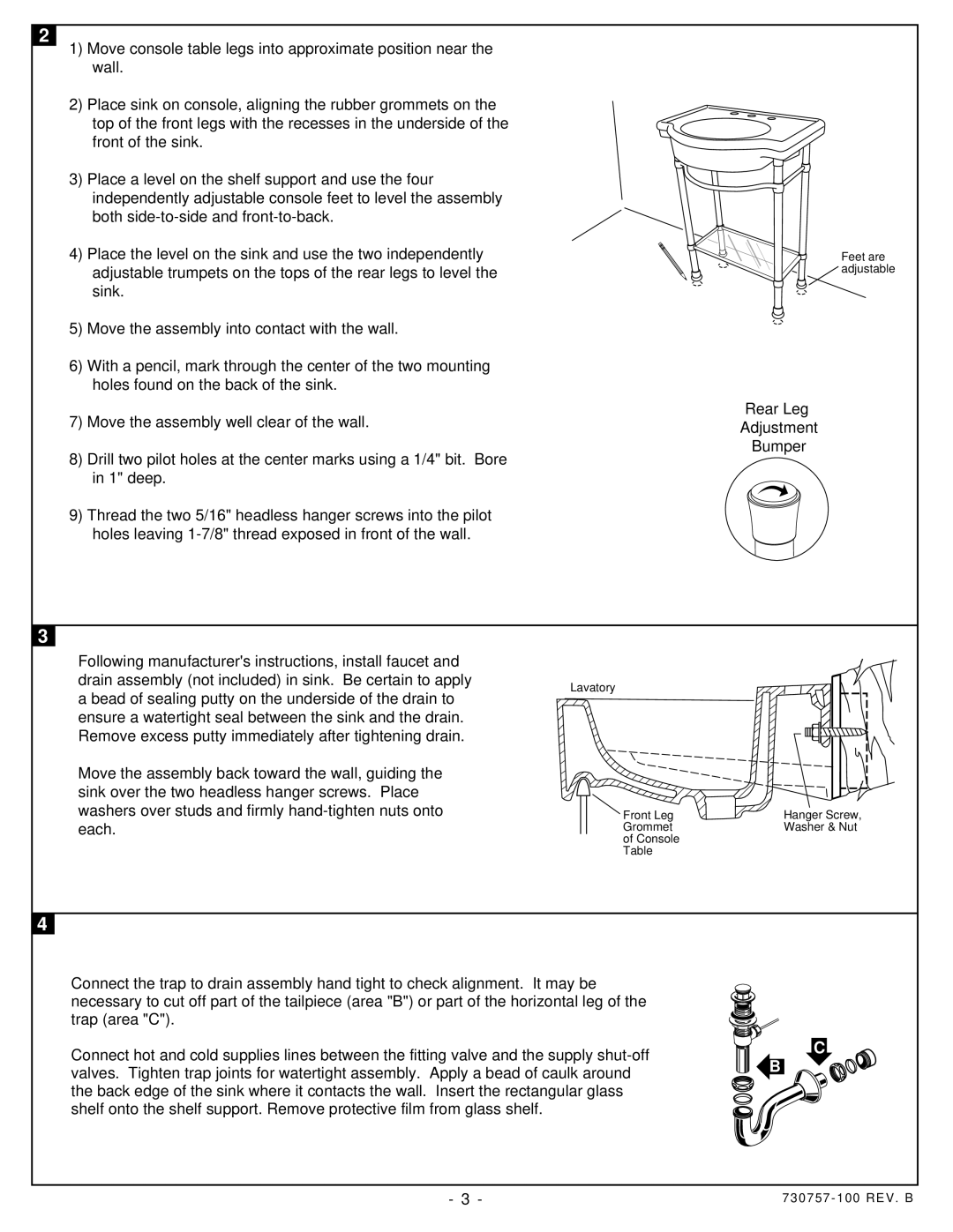
2)Place sink on console, aligning the rubber grommets on the top of the front legs with the recesses in the underside of the front of the sink.
3)Place a level on the shelf support and use the four independently adjustable console feet to level the assembly both
4)Place the level on the sink and use the two independently adjustable trumpets on the tops of the rear legs to level the sink.
5)Move the assembly into contact with the wall.
6)With a pencil, mark through the center of the two mounting holes found on the back of the sink.
7)Move the assembly well clear of the wall.
8)Drill two pilot holes at the center marks using a 1/4" bit. Bore in 1" deep.
9)Thread the two 5/16" headless hanger screws into the pilot holes leaving
Feet are  adjustable
Rear Leg
Adjustment
Bumper
3
Following manufacturer's instructions, install faucet and drain assembly (not included) in sink. Be certain to apply a bead of sealing putty on the underside of the drain to ensure a watertight seal between the sink and the drain. Remove excess putty immediately after tightening drain.
Move the assembly back toward the wall, guiding the sink over the two headless hanger screws. Place washers over studs and firmly
Lavatory
Front Leg | Hanger Screw, |
Grommet | Washer & Nut |
of Console |
|
Table |
|
4
4
Connect the trap to drain assembly hand tight to check alignment. It may be necessary to cut off part of the tailpiece (area "B") or part of the horizontal leg of the trap (area "C").
Connect hot and cold supplies lines between the fitting valve and the supply
C
B
- 3 - | 730757 - 100 REV . B |