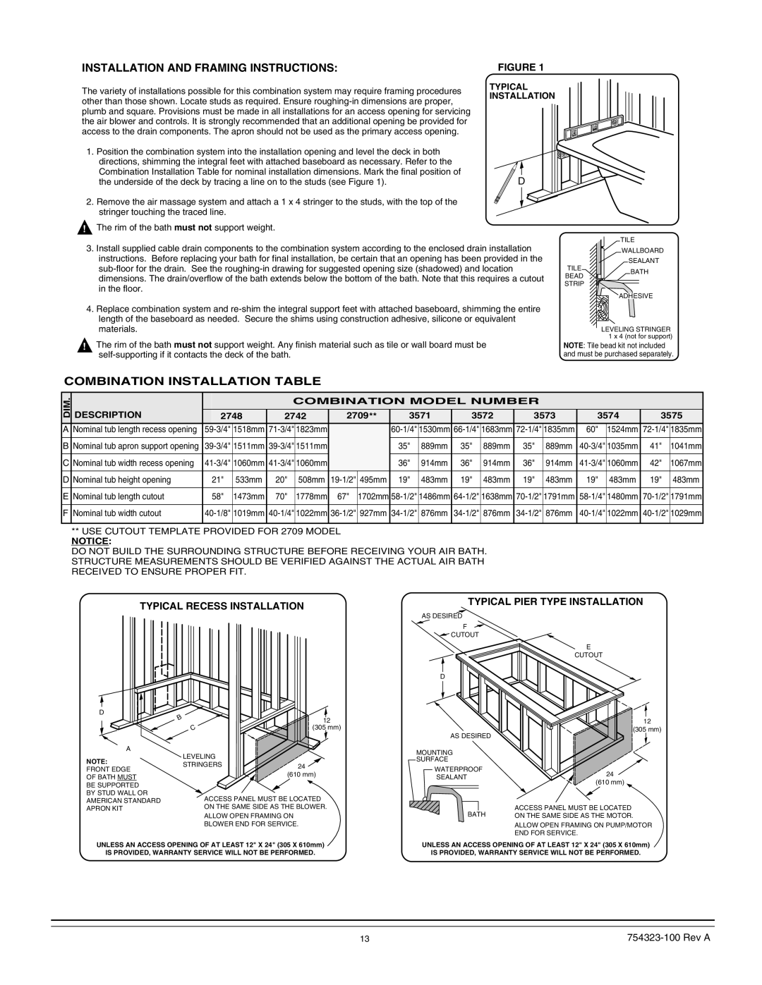
INSTALLATION AND FRAMING INSTRUCTIONS: | FIGURE 1 | |
The variety of installations possible for this combination system may require framing procedures | TYPICAL | |
INSTALLATION | ||
other than those shown. Locate studs as required. Ensure | ||
| ||
plumb and square. Provisions must be made in all installations for an access opening for servicing |
| |
the air blower and controls. It is strongly recommended that an additional opening be provided for |
| |
access to the drain components. The apron should not be used as the primary access opening. |
|
1.Position the combination system into the installation opening and level the deck in both directions, shimming the integral feet with attached baseboard as necessary. Refer to the Combination Installation Table for nominal installation dimensions. Mark the final position of
the underside of the deck by tracing a line on to the studs (see Figure 1). | D |
2. Remove the air massage system and attach a 1 x 4 stringer to the studs, with the top of the stringer touching the traced line.
!The rim of the bath must not support weight.
3.Install supplied cable drain components to the combination system according to the enclosed drain installation instructions. Before replacing your bath for final installation, be certain that an opening has been provided in the
4.Replace combination system and
!The rim of the bath must not support weight. Any finish material such as tile or wall board must be
| TILE | |
| WALLBOARD | |
TILE | SEALANT | |
BATH | ||
BEAD | ||
| ||
STRIP |
| |
| ADHESIVE | |
| LEVELING STRINGER | |
| 1 x 4 (not for support) |
NOTE: Tile bead kit not included and must be purchased separately.
COMBINATION INSTALLATION TABLE
DIM.
A
B
C
D
E
F
|
|
|
|
| COMBINATION MODEL NUMBER |
|
|
|
|
| ||||||||
DESCRIPTION |
| 2748 | 2742 | 2709** | 3571 | 3572 | 3573 | 3574 | 3575 | |||||||||
|
|
|
|
|
|
|
|
|
|
|
|
|
|
|
|
|
|
|
Nominal tub length recess opening | 1518mm | 1823mm |
|
| 1530mm | 1683mm | 1835mm | 60" | 1524mm | 1835mm | ||||||||
|
|
|
|
|
|
|
|
|
|
|
|
|
|
|
|
| ||
Nominal tub apron support opening | 1511mm | 1511mm |
|
| 35" | 889mm | 35" | 889mm | 35" | 889mm | 1035mm | 41" | 1041mm | |||||
|
|
|
|
|
|
|
|
|
|
|
|
|
|
|
|
| ||
Nominal tub width recess opening | 1060mm | 1060mm |
|
| 36" | 914mm | 36" | 914mm | 36" | 914mm | 1060mm | 42" | 1067mm | |||||
Nominal tub height opening | 21" | 533mm | 20" |
| 508mm | 495mm | 19" | 483mm | 19" | 483mm | 19" | 483mm | 19" | 483mm | 19" | 483mm | ||
Nominal tub length cutout | 58" | 1473mm | 70" |
| 1778mm | 67" | 1702mm | 1486mm | 1638mm | 1791mm | 1480mm | 1791mm | ||||||
Nominal tub width cutout | 1019mm | 1022mm | 927mm | 876mm | 876mm | 876mm | 1022mm | 1029mm | ||||||||||
|
|
|
|
|
|
|
|
|
|
|
|
|
|
|
|
|
|
|
**USE CUTOUT TEMPLATE PROVIDED FOR 2709 MODEL
NOTICE:
DO NOT BUILD THE SURROUNDING STRUCTURE BEFORE RECEIVING YOUR AIR BATH. STRUCTURE MEASUREMENTS SHOULD BE VERIFIED AGAINST THE ACTUAL AIR BATH RECEIVED TO ENSURE PROPER FIT.
TYPICAL RECESS INSTALLATION
TYPICAL PIER TYPE INSTALLATION
AS DESIRED
F
CUTOUT
D
E
CUTOUT
D
A
NOTE:
FRONT EDGE
OF BATH MUST
BE SUPPORTED BY STUD WALL OR AMERICAN STANDARD APRON KIT
B | 12 |
C | (305 mm) |
LEVELING
STRINGERS24 (610 mm)
ACCESS PANEL MUST BE LOCATED
ON THE SAME SIDE AS THE BLOWER.
ALLOW OPEN FRAMING ON
BLOWER END FOR SERVICE.
AS DESIRED
MOUNTING
SURFACE
WATERPROOF SEALANT
BATH
12
(305 mm)
24
(610 mm)
ACCESS PANEL MUST BE LOCATED ON THE SAME SIDE AS THE MOTOR.
ALLOW OPEN FRAMING ON PUMP/MOTOR END FOR SERVICE.
UNLESS AN ACCESS OPENING OF AT LEAST 12" X 24" (305 X 610mm)
IS PROVIDED, WARRANTY SERVICE WILL NOT BE PERFORMED.
UNLESS AN ACCESS OPENING OF AT LEAST 12" X 24" (305 X 610mm)
IS PROVIDED, WARRANTY SERVICE WILL NOT BE PERFORMED.
13 |