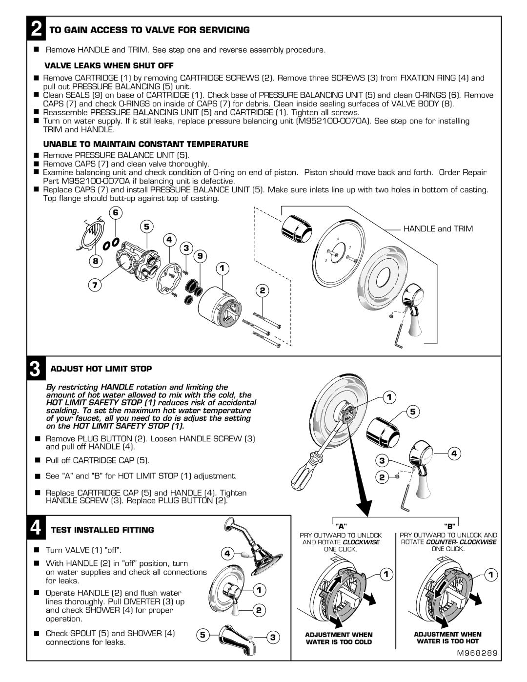
2 TO GAIN ACCESS TO VALVE FOR SERVICING
Remove HANDLE and TRIM. See step one and reverse assembly procedure.
VALVE LEAKS WHEN SHUT OFF
![]()
![]() Remove CARTRIDGE (1) by removing CARTRIDGE SCREWS (2). Remove three SCREWS (3) from FIXATION RING (4) and pull out PRESSURE BALANCING (5) unit.
Remove CARTRIDGE (1) by removing CARTRIDGE SCREWS (2). Remove three SCREWS (3) from FIXATION RING (4) and pull out PRESSURE BALANCING (5) unit.
![]()
![]() Clean SEALS (9) on base of CARTRIDGE (1). Check base of PRESSURE BALANCING UNIT (5) and clean
Clean SEALS (9) on base of CARTRIDGE (1). Check base of PRESSURE BALANCING UNIT (5) and clean
![]()
![]() Reassemble PRESSURE BALANCING UNIT (5) and CARTRIDGE (1). Tighten all screws.
Reassemble PRESSURE BALANCING UNIT (5) and CARTRIDGE (1). Tighten all screws.
![]()
![]() Turn on water supply. If it still leaks, replace pressure balancing unit
Turn on water supply. If it still leaks, replace pressure balancing unit
UNABLE TO MAINTAIN CONSTANT TEMPERATURE
Remove PRESSURE BALANCE UNIT (5). Remove CAPS (7) and clean valve thoroughly.
Examine balancing unit and check condition of
Replace CAPS (7) and install PRESSURE BALANCE UNIT (5). Make sure inlets line up with two holes in bottom of casting. Top flange should
6
5 | HANDLE and TRIM |
4
3
8
9
1
7
2
3 ADJUST HOT LIMIT STOP
By restricting HANDLE rotation and limiting the amount of hot water allowed to mix with the cold, the HOT LIMIT SAFETY STOP (1) reduces risk of accidental scalding. To set the maximum hot water temperature of your faucet, all you need to do is adjust the setting on the HOT LIMIT SAFETY STOP (1).
Remove PLUG BUTTON (2). Loosen HANDLE SCREW (3) and pull off HANDLE (4).
Pull off CARTRIDGE CAP (5).
See "A" and "B" for HOT LIMIT STOP (1) adjustment.
Replace CARTRIDGE CAP (5) and HANDLE (4). Tighten HANDLE SCREW (3). Replace PLUG BUTTON (2).
![]() 1
1
3
2
5
4
4 TEST INSTALLED FITTING |
|
|
Turn VALVE (1) "off". |
| 4 |
|
| |
With HANDLE (2) in "off" position, turn |
|
|
on water supplies and check all connections |
| |
for leaks. |
| 1 |
Operate HANDLE (2) and flush water |
| |
|
| |
lines thoroughly. Pull DIVERTER (3) up |
|
|
and check SHOWER (4) for proper |
| 2 |
operation. |
|
|
Check SPOUT (5) and SHOWER (4) | 5 | 3 |
connections for leaks. |
|
|
"A"
PRY OUTWARD TO UNLOCK AND ROTATE CLOCKWISE ONE CLICK.
![]() 1
1
ADJUSTMENT WHEN WATER IS TOO COLD
"B"
PRY OUTWARD TO UNLOCK AND ROTATE COUNTER- CLOCKWISE ONE CLICK.
![]() 1
1
ADJUSTMENT WHEN
WATER IS TOO HOT
M 9 6 8 2 8 9