GAS-FIRED COMMERCIAL WATER HEATER specifications
American Water Heater offers a range of high-performance gas-fired commercial water heaters designed to meet the needs of a variety of applications, including restaurants, hotels, and industrial facilities. Renowned for their reliability and efficiency, these water heaters are engineered to provide large volumes of hot water consistently and efficiently.One of the standout features of American Water Heater's gas-fired models is their robust construction. Built with durable materials, these heaters are designed to withstand the rigors of daily use in demanding commercial environments. The units typically have a high-quality glass-lined tank that enhances protection against corrosion, prolonging the water heater's lifespan and ensuring longevity.
Efficiency is at the core of American Water Heater's design ethos. Many models are equipped with advanced burner technologies that promote higher thermal efficiency. Some units boast energy factors exceeding industry standards, minimizing fuel consumption while maximizing output. This not only reduces operational costs but also contributes to environmental sustainability by lowering carbon emissions.
Among the innovative technologies incorporated into these water heaters is a precise temperature control system, which allows for the accurate regulation of hot water supply. This feature is crucial in commercial settings where the demand for hot water can fluctuate significantly. Moreover, features like digital diagnostics and integrated control systems make it easier for operators to monitor performance and troubleshoot problems swiftly, thus reducing downtime.
Safety is paramount in any gas-fired appliance, and American Water Heater prioritizes this with features such as automatic shutoff valves and flame failure protection systems. These safety mechanisms ensure that the units operate reliably while providing peace of mind to users.
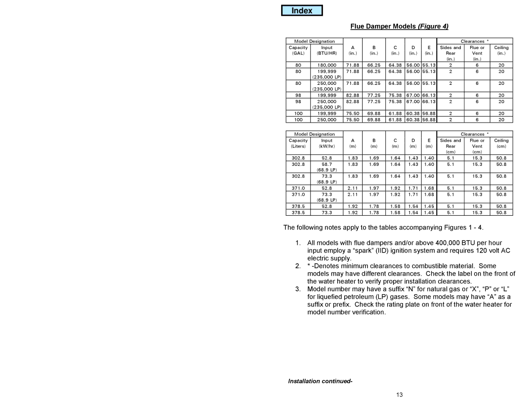
American Water Heater's gas-fired commercial water heaters also offer a range of capacities, catering to different operational needs. Models are available in various sizes, ensuring that no matter the volume of hot water required, there is a solution that fits.
In conclusion, American Water Heater's gas-fired commercial water heaters combine durability, efficiency, and advanced technology, making them suitable for a wide array of applications. With their focus on safety and performance, these units stand out as a top choice for businesses seeking a reliable hot water solution.
