SVT1000 Bass Amplifier
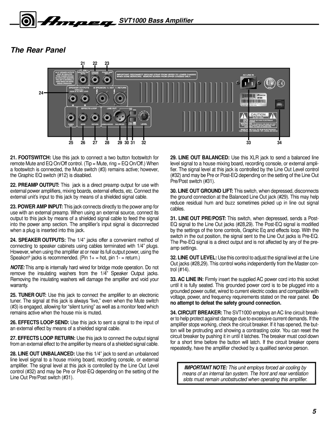
The Rear Panel
| 21 | 22 | 23 |
|
|
|
|
|
|
|
24 |
|
|
|
|
|
|
|
|
|
|
|
|
|
|
|
| 7 | 43565 | 15531 | 9 | SVT1000 |
|
|
|
|
|
|
| (21) | SERIAL# BMCDN20083 | ||
|
|
|
|
|
| Line: 120V Freq: 60 Pwr: XXXVA |
| |||
25 | 26 | 27 | 28 | 29 | 30 31 | 32 | 33 |
| 34 | |
21.FOOTSWITCH: Use this jack to connect a two button footswitch for remote Mute and EQ On/Off control. (Tip = Mute, ring = EQ On/Off.) When a footswitch is connected, the Mute switch (#3) remains active; however, the Graphic EQ switch (#12) is disabled.
22.PREAMP OUTPUT: This jack is a direct preamp output for use with external power amplifiers, mixing boards, external effects, etc. Connect the external unit’s input to this jack by means of a shielded signal cable.
23.POWER AMP INPUT: This jack connects directly to the power amp for use with an external preamp. When using an external source, connect its output to this jack by means of a shielded signal cable to feed the signal into the power amp section. The amplifier’s input signal is disconnected when a plug is inserted into this jack.
24.SPEAKER OUTPUTS: The 1/4” jacks offer a convenient method of connecting to speaker cabinets using cables terminated with 1/4” plugs. However, when using the amplifier at or near its full output power, using the Speakon® jacks is recommended. (Pin 1+ = hot, pin 1- = return.)
NOTE: This amp is internally hard wired for bridge mode operation. Do not remove the insulating washers from the 1/4” Speaker Output jacks. Removing the insulating washers will damage the amplifier and void your warranty.
25.TUNER OUT: Use this jack to connect the amplifier to an electronic tuner. The signal at this jack is always “live,” even when the Mute switch (#3) is engaged, allowing for “silent tuning” as well as a monitor feed which remains active when the house mix is muted.
26.EFFECTS LOOP SEND: Use this jack to sent a signal to the input of an external effect by means of a shielded signal cable.
27.EFFECTS LOOP RETURN: Use this jack to connect the output signal from an external effect to the amplifier by means of a shielded signal cable.
28.LINE OUT UNBALANCED: Use this 1/4” jack to send an unbalanced line level signal to a house mixing board, recording console, or external amplifier. The signal level at this jack is controlled by the Line Out Level control (#32) and may be Pre or
29.LINE OUT BALANCED: Use this XLR jack to send a balanced line level signal to a house mixing board, recording console, or external ampli- fier. The signal level at this jack is controlled by the Line Out Level control (#32) and may be Pre or
30.LINE OUT GROUND LIFT: This switch, when depressed, disconnects the ground connection at the Balanced Line Out jack (#29). This may help reduce residual hum and buzz sometimes picked up in line out signal cables.
31.LINE OUT PRE/POST: This switch, when depressed, sends a Post- EQ signal to the Line Out jacks (#28,29). The
32.LINE OUT LEVEL: Use this control to adjust the signal level at the Line Out jacks (#28,29). This control works independently from the Master con- trol (#14).
33.AC LINE IN: Firmly insert the supplied AC power cord into this socket until it is fully seated. This grounded power cord is to be plugged into a grounded power outlet, wired to current electric codes and compatible with voltage, power, and frequency requirements stated on the rear panel. Do no attempt to defeat the safety ground connection.
34.CIRCUIT BREAKER: The SVT1000 employs an AC line circuit break- er to help protect against damage due to excessive current demands. If the amplifier stops working, check the circuit breaker. If it has opened, the but- ton will be protruding and showing a contrasting color. You can reset the circuit breaker by pushing it in until it latches. The breaker must cool down for a short time before the button will latch. If the circuit breaker opens repeatedly, have the amplifier checked by a qualified service person.
IMPORTANT NOTE: This unit employs forced air cooling by means of an internal fan system. The front and rear ventilation slots must remain unobstructed when operating this amplifier.
5