Manuals
/
Amtrol
/
Household Appliance
/
Electric Heater
Amtrol
TD-7Z Installation Instructions For, A. General Installation Requirements, Locating Unit
Models:
TD-7ZDW
TD-41Z
TD-7Z
TD-41ZDW
1
6
16
16
Download
16 pages
30.41 Kb
3
4
5
6
7
8
9
10
Install
Zone Valves - Schematic
C. Electrical Wiring
Maintenance
Problem
Checklist
Replacement Parts
Safety
Service Record
Page 6
Image 6
Page 5
Page 7
Page 6
Image 6
Page 5
Page 7
Contents
MAINTENANCE
INDIRECT-FIREDWATER HEATERS WITH TOP-MOUNTEDCOIL
MODELS TD-7Z
INSTALLATION, OPERATION
PRE-INSTALLATIONCHECKLIST
TABLE OF CONTENTS
GENERAL SAFETY INFORMATION
REQUIRED COMPONENTS AND ACCESSORIES CHECKLIST
1. GENERAL SAFETY INFORMATION
2. PRE-INSTALLATIONCHECKLIST
3.REQUIRED COMPONENTS AND ACCESSORIES CHECKLIST
COMPONENTS CHECKLIST
TD-7Z, TD-41Z, TD-7ZDW, TD-41ZDW
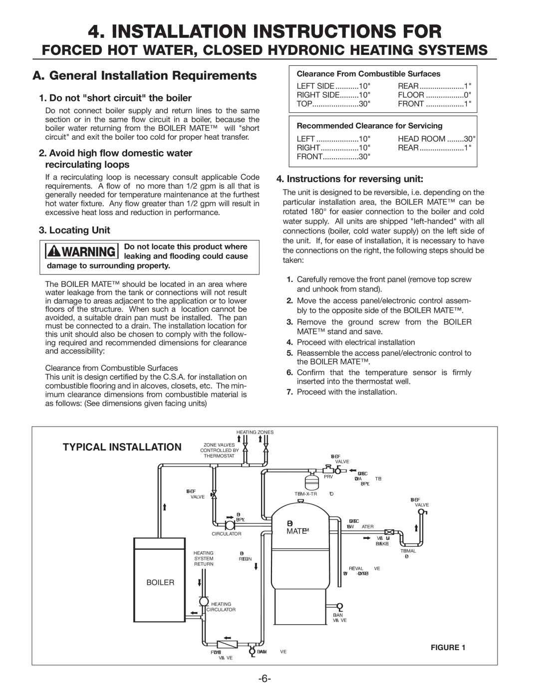
1. Do not short circuit the boiler
4. INSTALLATION INSTRUCTIONS FOR
A. General Installation Requirements
3. Locating Unit
INTERNAL TANKLESS COILS
B. PIPING
EXTERNAL TANKLESS HEATERS
Step 1 - Locate the BOILER MATE near boiler
Step 5 - Connect boiler supply pipe. Figure
II. BOILER MATE - Priority Wiring
SEPARATE CIRCULATOR
Step 6 - Connect boiler return pipe. Figure
ZONE VALVES - SCHEMATIC
D. POST-INSTALLATIONand START-UPCHECKLIST
TEMPERATURE ADJUSTMENT
PRIORITY W/CIRCULATORS - SCHEMATIC
Page
6. OPERATION/MAINTENANCE
AND LOW PRESSURE STEAM BOILER
TD-7Zand TD-41Z
7. REPLACEMENT PARTS
RESIDENTIAL BOILER MATE CLASSIC
DESCRIPTION
SOLUTION
8. TROUBLE SHOOTING CHECKLIST
PROBLEM
CAUSE
DATE
9. SERVICE RECORD
SERVICE PERFORMED
COMMENTS
Additional Warranty Limitations
LIMITED FIVE YEAR COMMERCIAL WARRANTY
LIMITED FIVE YEAR TRANSFERRABLE WARRANTY
Replacement Product Warranty
West Warwick, Rhode Island
9040-628REV B 7/04
Top
Page
Image
Contents