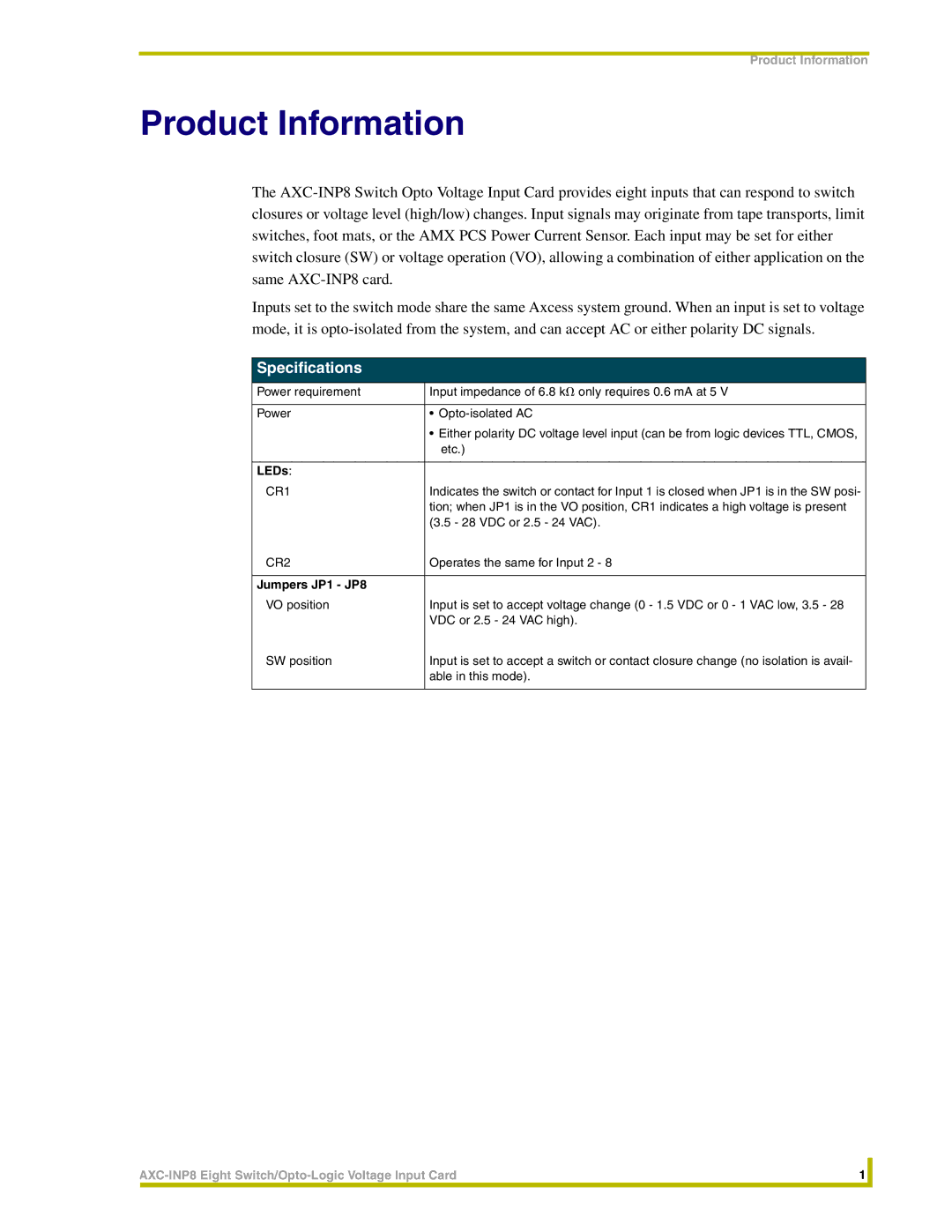
AXC-INP8 specifications
The AMX AXC-INP8 is a compact yet highly capable input processing device designed to integrate seamlessly within modern AV control and automation systems. As part of AMX’s renowned range of products, the AXC-INP8 is specifically engineered to enhance flexibility and expand the input capabilities of AV systems in various environments, including classrooms, conference rooms, and large venues.One of the standout features of the AXC-INP8 is its ability to support up to eight individual input connections. These inputs enable the device to accommodate various types of sources, such as HDMI, VGA, and audio connections, providing users with the versatility necessary for diverse AV applications. This multi-input functionality makes it ideal for environments where multiple presentations or media sources need to be accessed and managed easily.
The AXC-INP8 integrates advanced video scaling technology, allowing it to handle differing resolutions and formats efficiently. This feature ensures compatibility with a range of display technologies while maintaining high image quality, thus eliminating common issues like lag or distortion during presentations.
In terms of connectivity, the AXC-INP8 includes multiple output options to facilitate smooth integration with existing AV infrastructures. Its compatibility with AMX’s control systems allows for straightforward management of all connected devices, further simplifying operations for end users. The device also supports Ethernet connectivity, enabling remote management and monitoring, which is increasingly important in today’s networked environments.
Power over Ethernet (PoE) capability is another significant advantage of the AXC-INP8. This technology simplifies installation by allowing the device to be powered through the same Ethernet cable used for data transmission, reducing clutter while providing a cleaner setup.
The AXC-INP8 boasts a user-friendly interface, designed for ease of operation. Its intuitive layout and accessible controls allow users to switch between inputs seamlessly, making it an ideal solution for fast-paced settings where quick adjustments are necessary.
In conclusion, the AMX AXC-INP8 input processor combines advanced technology, versatile input support, and user-friendly features, making it an essential component for any modern AV installation. Its focus on flexibility and integration positions it as a reliable solution for a variety of applications in diverse environments, meeting the needs of contemporary AV professionals with excellence.

