Installation Guide
DAS-MNET Mi-Series Network Interface Card
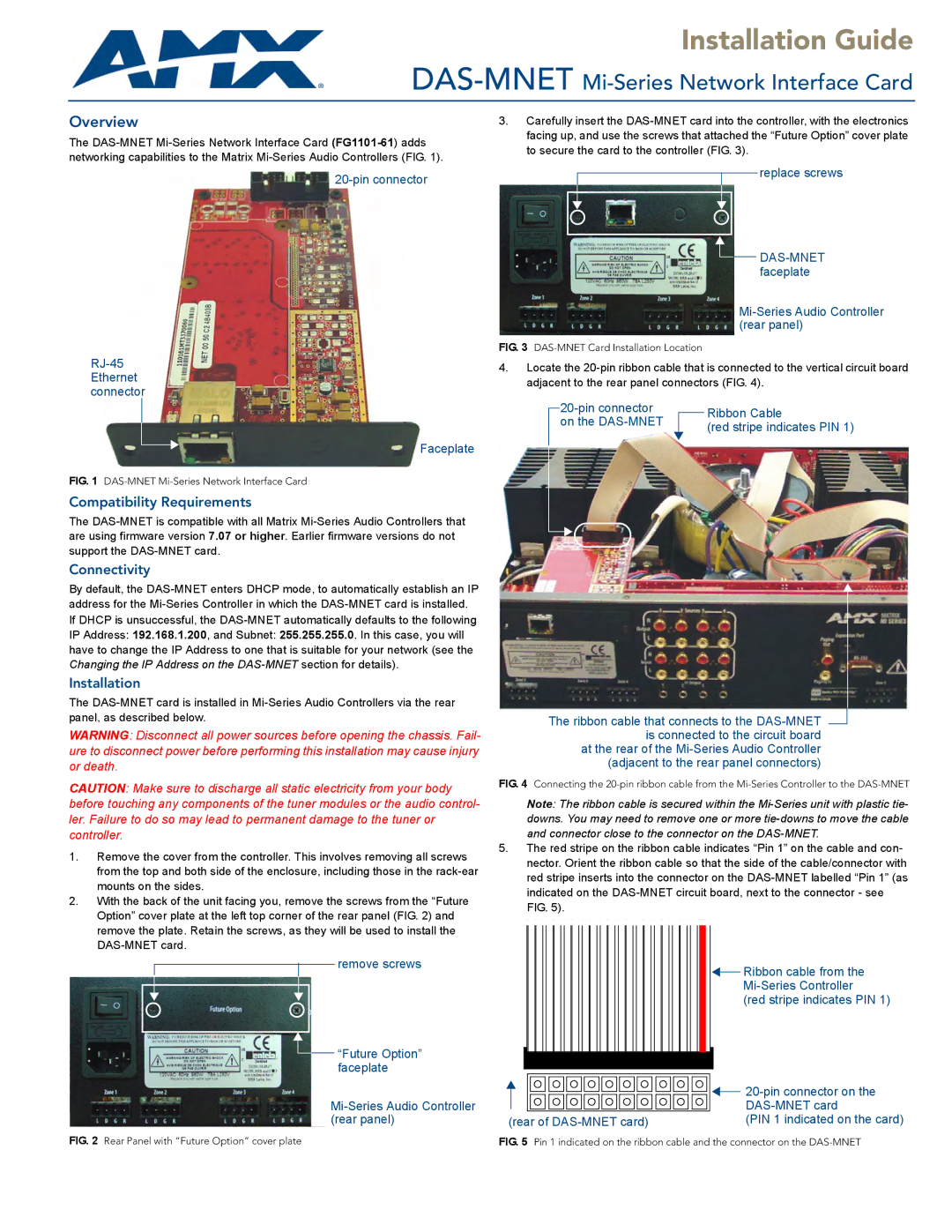
Overview
The
Faceplate
FIG. 1 DAS-MNET Mi-Series Network Interface Card
Compatibility Requirements
The
Connectivity
By default, the
Installation
The
WARNING: Disconnect all power sources before opening the chassis. Fail- ure to disconnect power before performing this installation may cause injury or death.
CAUTION: Make sure to discharge all static electricity from your body before touching any components of the tuner modules or the audio control- ler. Failure to do so may lead to permanent damage to the tuner or controller.
1.Remove the cover from the controller. This involves removing all screws from the top and both side of the enclosure, including those in the
2.With the back of the unit facing you, remove the screws from the “Future Option” cover plate at the left top corner of the rear panel (FIG. 2) and remove the plate. Retain the screws, as they will be used to install the
remove screws
![]()
![]() “Future Option” faceplate
“Future Option” faceplate
Mi-Series Audio Controller (rear panel)
3.Carefully insert the
replace screws
![]()
![]()
FIG. 3 DAS-MNET Card Installation Location
4.Locate the
| Ribbon Cable | |
on the |
| |
| (red stripe indicates PIN 1) | |
|
|
The ribbon cable that connects to the
(adjacent to the rear panel connectors)
FIG. 4 Connecting the 20-pin ribbon cable from the Mi-Series Controller to the DAS-MNET
Note: The ribbon cable is secured within the
5.The red stripe on the ribbon cable indicates “Pin 1” on the cable and con- nector. Orient the ribbon cable so that the side of the cable/connector with red stripe inserts into the connector on the
Ribbon cable from the |
(red stripe indicates PIN 1) |
|
|
|
|
| |
|
|
|
|
| |
(rear of |
|
| (PIN 1 indicated on the card) | ||
FIG. 2 Rear Panel with “Future Option” cover plate | FIG. 5 Pin 1 indicated on the ribbon cable and the connector on the |