Mounting Procedures
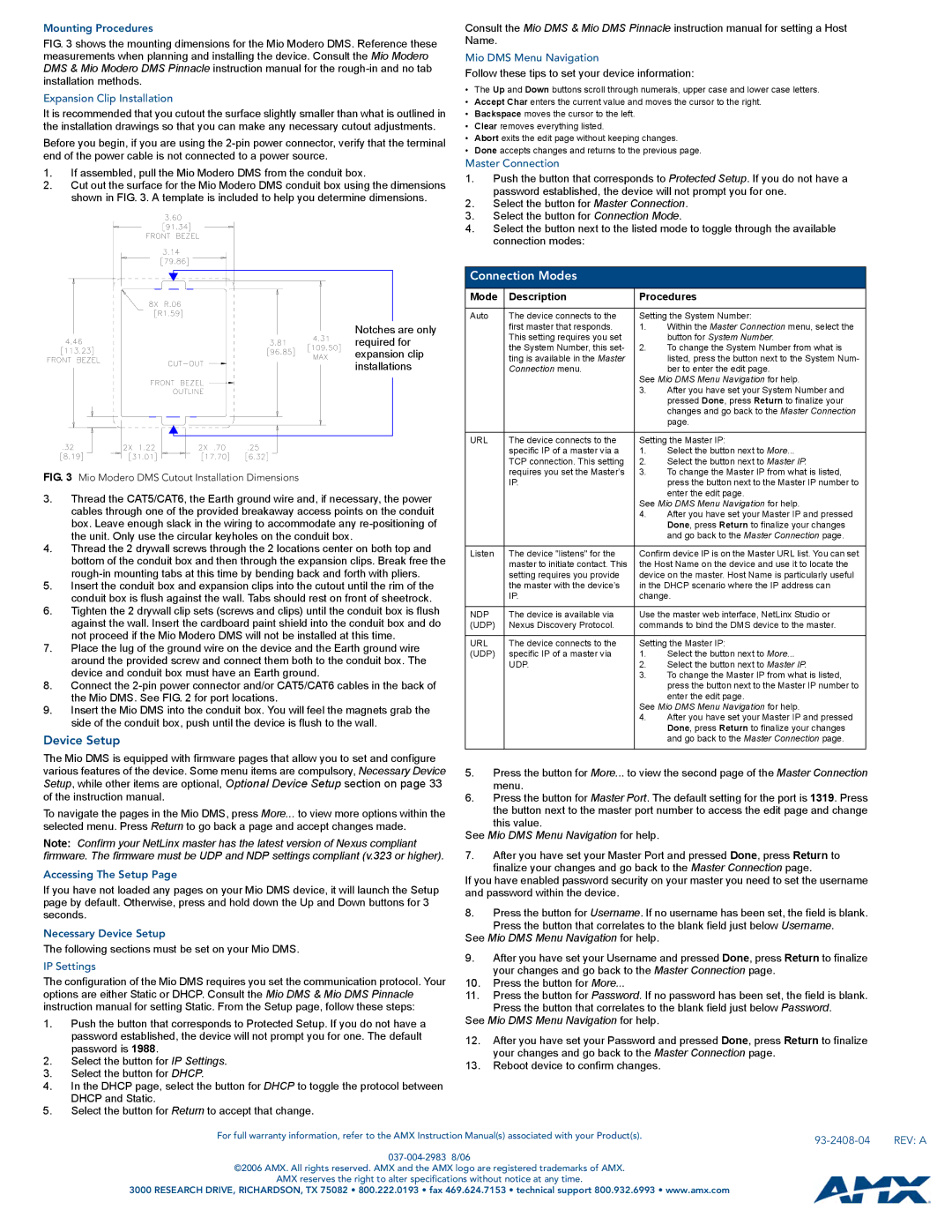
FIG. 3 shows the mounting dimensions for the Mio Modero DMS. Reference these measurements when planning and installing the device. Consult the Mio Modero DMS & Mio Modero DMS Pinnacle instruction manual for the
Expansion Clip Installation
It is recommended that you cutout the surface slightly smaller than what is outlined in the installation drawings so that you can make any necessary cutout adjustments.
Before you begin, if you are using the
1.If assembled, pull the Mio Modero DMS from the conduit box.
2.Cut out the surface for the Mio Modero DMS conduit box using the dimensions shown in FIG. 3. A template is included to help you determine dimensions.
Notches are only required for expansion clip installations
FIG. 3 Mio Modero DMS Cutout Installation Dimensions
3.Thread the CAT5/CAT6, the Earth ground wire and, if necessary, the power cables through one of the provided breakaway access points on the conduit box. Leave enough slack in the wiring to accommodate any
4.Thread the 2 drywall screws through the 2 locations center on both top and bottom of the conduit box and then through the expansion clips. Break free the
5.Insert the conduit box and expansion clips into the cutout until the rim of the conduit box is flush against the wall. Tabs should rest on front of sheetrock.
6.Tighten the 2 drywall clip sets (screws and clips) until the conduit box is flush against the wall. Insert the cardboard paint shield into the conduit box and do not proceed if the Mio Modero DMS will not be installed at this time.
7.Place the lug of the ground wire on the device and the Earth ground wire around the provided screw and connect them both to the conduit box. The device and conduit box must have an Earth ground.
8.Connect the
9.Insert the Mio DMS into the conduit box. You will feel the magnets grab the side of the conduit box, push until the device is flush to the wall.
Device Setup
Consult the Mio DMS & Mio DMS Pinnacle instruction manual for setting a Host Name.
Mio DMS Menu Navigation
Follow these tips to set your device information:
•The Up and Down buttons scroll through numerals, upper case and lower case letters.
•Accept Char enters the current value and moves the cursor to the right.
•Backspace moves the cursor to the left.
•Clear removes everything listed.
•Abort exits the edit page without keeping changes.
•Done accepts changes and returns to the previous page.
Master Connection
1.Push the button that corresponds to Protected Setup. If you do not have a password established, the device will not prompt you for one.
2.Select the button for Master Connection.
3.Select the button for Connection Mode.
4.Select the button next to the listed mode to toggle through the available connection modes:
Connection Modes
Mode | Description | Procedures | |
|
|
| |
Auto | The device connects to the | Setting the System Number: | |
| first master that responds. | 1. | Within the Master Connection menu, select the |
| This setting requires you set |
| button for System Number. |
| the System Number, this set- | 2. | To change the System Number from what is |
| ting is available in the Master |
| listed, press the button next to the System Num- |
| Connection menu. |
| ber to enter the edit page. |
|
| See Mio DMS Menu Navigation for help. | |
|
| 3. | After you have set your System Number and |
|
|
| pressed Done, press Return to finalize your |
|
|
| changes and go back to the Master Connection |
|
|
| page. |
|
|
| |
URL | The device connects to the | Setting the Master IP: | |
| specific IP of a master via a | 1. | Select the button next to More... |
| TCP connection. This setting | 2. | Select the button next to Master IP. |
| requires you set the Master’s | 3. | To change the Master IP from what is listed, |
| IP. |
| press the button next to the Master IP number to |
|
|
| enter the edit page. |
|
| See Mio DMS Menu Navigation for help. | |
|
| 4. | After you have set your Master IP and pressed |
|
|
| Done, press Return to finalize your changes |
|
|
| and go back to the Master Connection page. |
|
|
| |
Listen | The device "listens" for the | Confirm device IP is on the Master URL list. You can set | |
| master to initiate contact. This | the Host Name on the device and use it to locate the | |
| setting requires you provide | device on the master. Host Name is particularly useful | |
| the master with the device’s | in the DHCP scenario where the IP address can | |
| IP. | change. | |
|
|
| |
NDP | The device is available via | Use the master web interface, NetLinx Studio or | |
(UDP) | Nexus Discovery Protocol. | commands to bind the DMS device to the master. | |
|
|
| |
URL | The device connects to the | Setting the Master IP: | |
(UDP) | specific IP of a master via | 1. | Select the button next to More... |
| UDP. | 2. | Select the button next to Master IP. |
|
| 3. | To change the Master IP from what is listed, |
|
|
| press the button next to the Master IP number to |
|
|
| enter the edit page. |
|
| See Mio DMS Menu Navigation for help. | |
|
| 4. | After you have set your Master IP and pressed |
|
|
| Done, press Return to finalize your changes |
|
|
| and go back to the Master Connection page. |
|
|
|
|
The Mio DMS is equipped with firmware pages that allow you to set and configure various features of the device. Some menu items are compulsory, Necessary Device Setup, while other items are optional, Optional Device Setup section on page 33 of the instruction manual.
To navigate the pages in the Mio DMS, press More... to view more options within the selected menu. Press Return to go back a page and accept changes made.
Note: Confirm your NetLinx master has the latest version of Nexus compliant firmware. The firmware must be UDP and NDP settings compliant (v.323 or higher).
Accessing The Setup Page
If you have not loaded any pages on your Mio DMS device, it will launch the Setup page by default. Otherwise, press and hold down the Up and Down buttons for 3 seconds.
Necessary Device Setup
The following sections must be set on your Mio DMS.
IP Settings
The configuration of the Mio DMS requires you set the communication protocol. Your options are either Static or DHCP. Consult the Mio DMS & Mio DMS Pinnacle instruction manual for setting Static. From the Setup page, follow these steps:
1.Push the button that corresponds to Protected Setup. If you do not have a password established, the device will not prompt you for one. The default password is 1988.
2.Select the button for IP Settings.
3.Select the button for DHCP.
4.In the DHCP page, select the button for DHCP to toggle the protocol between DHCP and Static.
5.Select the button for Return to accept that change.
5.Press the button for More... to view the second page of the Master Connection menu.
6.Press the button for Master Port. The default setting for the port is 1319. Press the button next to the master port number to access the edit page and change
this value.
See Mio DMS Menu Navigation for help.
7.After you have set your Master Port and pressed Done, press Return to finalize your changes and go back to the Master Connection page.
If you have enabled password security on your master you need to set the username and password within the device.
8.Press the button for Username. If no username has been set, the field is blank.
Press the button that correlates to the blank field just below Username. See Mio DMS Menu Navigation for help.
9.After you have set your Username and pressed Done, press Return to finalize your changes and go back to the Master Connection page.
10.Press the button for More...
11.Press the button for Password. If no password has been set, the field is blank. Press the button that correlates to the blank field just below Password.
See Mio DMS Menu Navigation for help.
12.After you have set your Password and pressed Done, press Return to finalize your changes and go back to the Master Connection page.
13.Reboot device to confirm changes.
For full warranty information, refer to the AMX Instruction Manual(s) associated with your Product(s). |
| REV: A |
|
©2006 AMX. All rights reserved. AMX and the AMX logo are registered trademarks of AMX.
AMX reserves the right to alter specifications without notice at any time.
3000 RESEARCH DRIVE, RICHARDSON, TX 75082 • 800.222.0193 • fax 469.624.7153 • technical support 800.932.6993 • www.amx.com