Quick Start Guide

Mio Modero DMS Keypad

Overview

Installation

The Mio Modero DMS device family provides a wide range of control capabilities in the form of user specified buttons that are functional yet recherché.

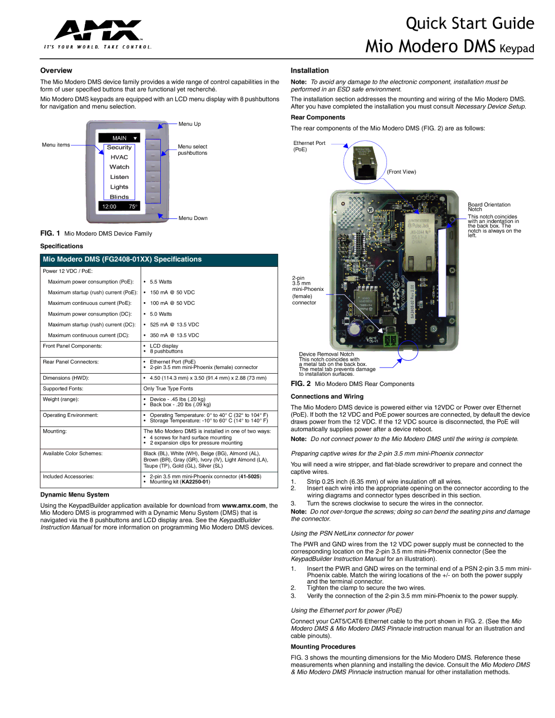
Mio Modero DMS keypads are equipped with an LCD menu display with 8 pushbuttons for navigation and menu selection.

Note: To avoid any damage to the electronic component, installation must be performed in an ESD safe environment.

The installation section addresses the mounting and wiring of the Mio Modero DMS. After you have completed the installation you must consult Necessary Device Setup.

Rear Components

Menu items

Menu Up

Menu select pushbuttons

Menu Down

The rear components of the Mio Modero DMS (FIG. 2) are as follows:

Ethernet Port (PoE)

(Front View)

Board Orientation Notch

This notch coincides with an indentation in the back box. The

FIG. 1 Mio Modero DMS Device Family

Specifications

Mio Modero DMS (FG2408-01XX) Specifications

Power 12 VDC / PoE:


Maximum power consumption (PoE):

5.5 Watts

Maximum startup (rush) current (PoE):

• 150 mA @ 50 VDC

Maximum continuous current (PoE):

• 100 mA @ 50 VDC

Maximum power consumption (DC):

5.0 Watts

Maximum startup (rush) current (DC):

• 525 mA @ 13.5 VDC

Maximum continuous current (DC):

• 350 mA @ 13.5 VDC


Front Panel Components:

LCD display


8 pushbuttons


Rear Panel Connectors:

Ethernet Port (PoE)


2-pin 3.5 mm mini-Phoenix (female) connector


Dimensions (HWD):

• 4.50 (114.3 mm) x 3.50 (91.4 mm) x 2.88 (73 mm)


Supported Fonts:

Only True Type Fonts


Weight (range):

• Device - .45 lbs (.20 kg)


• Back box - .20 lbs (.09 kg)


Operating Environment:

• Operating Temperature: 0° to 40° C (32° to 104° F)


• Storage Temperature: -10° to 60° C (14° to 140° F)


Mounting:

The Mio Modero DMS is installed in one of two ways:


• 4 screws for hard surface mounting


• 2 expansion clips for pressure mounting


Available Color Schemes:

Black (BL), White (WH), Beige (BG), Almond (AL),


Brown (BR), Gray (GR), Ivory (IV), Light Almond (LA),


Taupe (TP), Gold (GL), Silver (SL)


Included Accessories:

2-pin 3.5 mm mini-Phoenix connector (41-5025)


Mounting kit (KA2250-01)


Dynamic Menu System

Using the KeypadBuilder application available for download from www.amx.com, the Mio Modero DMS is programmed with a Dynamic Menu System (DMS) that is navigated via the 8 pushbuttons and LCD display area. See the KeypadBuilder Instruction Manual for more information on programming Mio Modero DMS devices.

notch is always on the left.

2-pin

3.5 mm mini-Phoenix

(female) connector

Device Removal Notch

This notch coincides with

a metal tab on the back box. The metal tab prevents damage to installation surfaces.

FIG. 2 Mio Modero DMS Rear Components

Connections and Wiring

The Mio Modero DMS device is powered either via 12VDC or Power over Ethernet (PoE). If both the 12 VDC and PoE power sources are connected, by default the device draws power from the 12 VDC. If the 12 VDC source is disconnected, the PoE will automatically supplies power after a device reboot.

Note: Do not connect power to the Mio Modero DMS until the wiring is complete.

Preparing captive wires for the 2-pin 3.5 mm mini-Phoenix connector

You will need a wire stripper, and flat-blade screwdriver to prepare and connect the captive wires.

1.Strip 0.25 inch (6.35 mm) of wire insulation off all wires.

2.Insert each wire into the appropriate opening on the connector according to the wiring diagrams and connector types described in this section.

3.Turn the screws clockwise to secure the wires in the connector.

Note: Do not over-torque the screws; doing so can bend the seating pins and damage the connector.

Using the PSN NetLinx connector for power

The PWR and GND wires from the 12 VDC power supply must be connected to the corresponding location on the 2-pin 3.5 mm mini-Phoenix connector (See the KeypadBuilder Instruction Manual for an illustration).

1.Insert the PWR and GND wires on the terminal end of a PSN 2-pin 3.5 mm mini- Phoenix cable. Match the wiring locations of the +/- on both the power supply and the terminal connector.

2.Tighten the clamp to secure the two wires.

3.Verify the connection of the 2-pin 3.5 mm mini-Phoenix to the power supply.

Using the Ethernet port for power (PoE)

Connect your CAT5/CAT6 Ethernet cable to the port shown in FIG. 2. (See the Mio Modero DMS & Mio Modero DMS Pinnacle instruction manual for an illustration and cable pinouts).

Mounting Procedures

FIG. 3 shows the mounting dimensions for the Mio Modero DMS. Reference these measurements when planning and installing the device. Consult the Mio Modero DMS

&Mio Modero DMS Pinnacle instruction manual for other installation methods.

Page 1
Image 1
AMX Dms Keypad quick start Rear Components, Specifications, Dynamic Menu System, Connections and Wiring

Dms Keypad specifications

The AMX DMS Keypad stands out as a vital component in the realm of control systems, providing intuitive management over various audiovisual environments. This keypad is designed to help users effortlessly manage their AV setups in commercial and residential spaces, making it an essential tool for both integrators and end-users.

One of the primary features of the AMX DMS Keypad is its sleek, modern design, which allows it to blend seamlessly with any décor. This aesthetic appeal, coupled with its functional abilities, ensures it meets the expectations of contemporary users. The keypad typically features customizable overlays, allowing organizations to tailor button layouts according to specific needs, thereby enhancing the user experience.

Equipped with advanced communication technologies, the AMX DMS Keypad supports both wired and wireless connectivity options. This flexibility not only simplifies installation but also allows for greater adaptability in various environments. The keypad integrates seamlessly with AMX’s extensive range of control systems, ensuring smooth interoperability and reliable performance across multiple devices.

Another significant characteristic of the DMS Keypad is its user-friendly interface, making it accessible even to those who may not be tech-savvy. The buttons are typically backlit, enabling easy visibility in dimly lit conditions, which is crucial in environments such as auditoriums or conference rooms.

In terms of functionality, the AMX DMS Keypad supports a variety of control options, including volume adjustments, source selection, and lighting control. This multi-functionality allows users to manage their AV systems with a single device, streamlining operations and enhancing overall efficiency. Moreover, the keypad can be programmed to execute complex commands or macros, providing users with a versatile tool tailored to their operational needs.

Another advantage is its integration capabilities with third-party devices, further extending its functionality. This allows users to not only control AMX systems but also coordinate with other technology brands, promoting a more cohesive technology ecosystem.

In conclusion, the AMX DMS Keypad is an exceptional piece of technology designed to simplify the management of audiovisual systems. Its blend of modern aesthetics, user-friendly design, extensive integration options, and advanced communication technologies make it an invaluable asset for any AV professional. Whether in a corporate office, educational institution, or entertainment venue, the DMS Keypad enhances both usability and functionality, creating a seamless user experience.