BEZEL OUTLINE
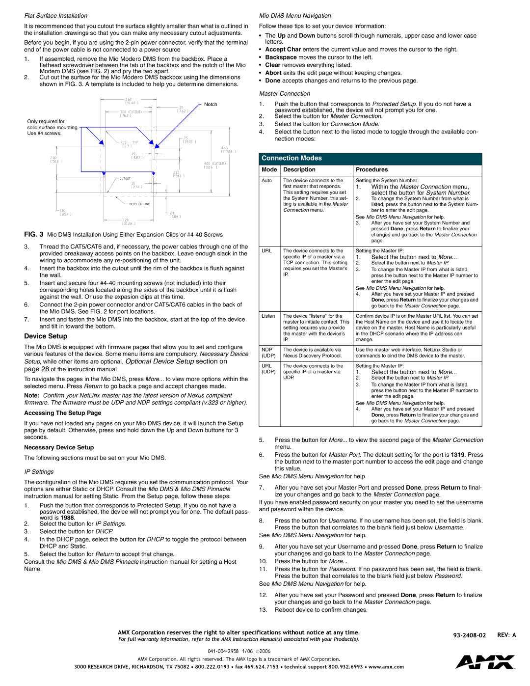
FIG. 3 Mio DMS Installation Using Either Expansion Clips or #4-40 Screws
3.Thread the CAT5/CAT6 and, if necessary, the power cables through one of the provided breakaway access points on the backbox. Leave enough slack in the wiring to accommodate any re-positioning of the unit.
4.Insert the backbox into the cutout until the rim of the backbox is flush against the wall.
5.Insert and secure four #4-40 mounting screws (not included) into their corresponding holes located along the sides of the backbox until it is flush against the wall. Or use the expasion clips at this time.
6.Connect the 2-pin power connector and/or CAT5/CAT6 cables in the back of the Mio DMS. See FIG. 2 for port locations.
7.Insert and fasten the Mio DMS into the backbox, start at the top of the device and tilt in toward the bottom.
Device Setup
The Mio DMS is equipped with firmware pages that allow you to set and configure various features of the device. Some menu items are compulsory, Necessary Device Setup, while other items are optional, Optional Device Setup section on page 28 of the instruction manual.
To navigate the pages in the Mio DMS, press More... to view more options within the selected menu. Press Return to go back a page and accept changes made.
Note: Confirm your NetLinx master has the latest version of Nexus compliant firmware. The firmware must be UDP and NDP settings compliant (v.323 or higher).
Accessing The Setup Page
If you have not loaded any pages on your Mio DMS device, it will launch the Setup page by default. Otherwise, press and hold down the Up and Down buttons for 3 seconds.
Necessary Device Setup
The following sections must be set on your Mio DMS.
IP Settings
The configuration of the Mio DMS requires you set the communication protocol. Your options are either Static or DHCP. Consult the Mio DMS & Mio DMS Pinnacle instruction manual for setting Static. From the Setup page, follow these steps:
1.Push the button that corresponds to Protected Setup. If you do not have a password established, the device will not prompt you for one. The default pass- word is 1988.
2.Select the button for IP Settings.
3.Select the button for DHCP.
4.In the DHCP page, select the button for DHCP to toggle the protocol between DHCP and Static.
5.Select the button for Return to accept that change.
Consult the Mio DMS & Mio DMS Pinnacle instruction manual for setting a Host Name.
| ting is available in the Master | | listed, press the button next to the System Num- |
| Connection menu. | | ber to enter the edit page. |
| | See Mio DMS Menu Navigation for help. |
| | 3. | After you have set your System Number and |
| | | pressed Done, press Return to finalize your |
| | | changes and go back to the Master Connection |
| | | page. |
| | |
URL | The device connects to the | Setting the Master IP: |
| specific IP of a master via a | 1. | Select the button next to More... |
| TCP connection. This setting | 2. | Select the button next to Master IP. |
| requires you set the Master’s | 3. | To change the Master IP from what is listed, |
| IP. | | press the button next to the Master IP number to |
| | | enter the edit page. |
| | See Mio DMS Menu Navigation for help. |
| | 4. | After you have set your Master IP and pressed |
| | | Done, press Return to finalize your changes and |
| | | go back to the Master Connection page. |
| | |
Listen | The device "listens" for the | Confirm device IP is on the Master URL list. You can set |
| master to initiate contact. This | the Host Name on the device and use it to locate the |
| setting requires you provide | device on the master. Host Name is particularly useful |
| the master with the device’s | in the DHCP scenario where the IP address can |
| IP. | change. |
| | |
NDP | The device is available via | Use the master web interface, NetLinx Studio or |
(UDP) | Nexus Discovery Protocol. | commands to bind the DMS device to the master. |
| | |
URL | The device connects to the | Setting the Master IP: |
(UDP) | specific IP of a master via | 1. | Select the button next to More... |
| UDP. | 2. | Select the button next to Master IP. |
| | 3. | To change the Master IP from what is listed, |
| | | press the button next to the Master IP number to |
| | | enter the edit page. |
| | See Mio DMS Menu Navigation for help. |
| | 4. | After you have set your Master IP and pressed |
| | | Done, press Return to finalize your changes and |
| | | go back to the Master Connection page. |
5.Press the button for More... to view the second page of the Master Connection menu.
6.Press the button for Master Port. The default setting for the port is 1319. Press the button next to the master port number to access the edit page and change this value.
See Mio DMS Menu Navigation for help.
7.After you have set your Master Port and pressed Done, press Return to final- ize your changes and go back to the Master Connection page.
If you have enabled password security on your master you need to set the username and password within the device.
8.Press the button for Username. If no username has been set, the field is blank. Press the button that correlates to the blank field just below Username.
See Mio DMS Menu Navigation for help.
9.After you have set your Username and pressed Done, press Return to finalize your changes and go back to the Master Connection page.
10.Press the button for More...
11.Press the button for Password. If no password has been set, the field is blank. Press the button that correlates to the blank field just below Password.
See Mio DMS Menu Navigation for help.
12.After you have set your Password and pressed Done, press Return to finalize your changes and go back to the Master Connection page.
13.Reboot device to confirm changes.