Step 1: Connect a Mouse, Keyboard and VGA Monitor
Connect a PS/2 mouse and keyboard, and a VGA monitor directly to the server to access the
Note: Alternatively, you can access the MAX Admin Menu via Telnet, using the Server Configuration feature in the WInMAX software. This requires that the server is configured with an IP address and Subnet Mask settings which are appropriate for your network configuration. Refer to “Step 6: Install and Configure WinMAX Software” for details.
Step 2: Connect the Power Cable and Apply Power
Note: It is recommended that you use a UPS with the
1.Connect the power supply, using the supplied power cord.
2.Flip the Master Power switch to the On position.
3.Push the Power On/Off toggle switch to apply power.
4.Allow up to one minute for the server to
Shutting Down the MAX-HT Server
Always shut down the server via the Shutdown command in the MAX Admin Menu (see below). This allows the operating system to shut down completely before power is removed, and prevents the
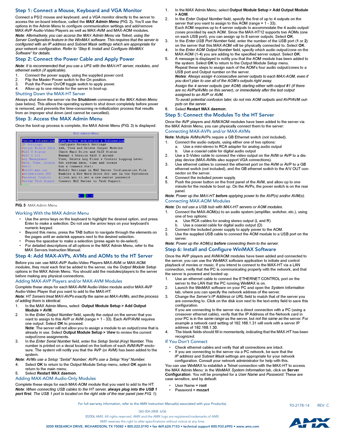
Step 3: Access the MAX Admin Menu
Once the
1.In the MAX Admin Menu, select Output Module Setup > Add Output Module > AOM.
2.In the Enter Output Number field, specify the first of up to 4 outputs on the server that you want to assign to this AOM (range = 1 - 33).
Each AOM requires up to 4 server outputs to accommodate the 4 audio output/ zones provided by each AOM. Since the
3.In the Enter USB Port Number field, enter the number of the USB port (1 or 2) on the server that this
4.In the Enter AOM Output Number field, specify which audio output/zone on the
5.A message is displayed to notify you that the AOM module has been added to the system. Select OK to return to the Output Module Setup menu.
Repeat these steps to assign each of the AOM’s four audio output/zones to a USB port and Output number on the server.
Notes: Always assign 4 consecutive server outputs to each
Assign the 4 server outputs (per AOM) starting either with output #1 (if there are no AVPs/AVMs on this server), or immediately after the last output assigned to an AVP or AVM.
To avoid potential confusion later, do not mix AOM outputs and AVP/AVM out- puts on the server.
6.Select Restart MAX daemon.
Step 5: Connect the Modules To the HT Server
Once the AVP players and AVM/AOM modules have been added to the server via the MAX Admin Menu, you can physically connect them to the server:
FIG. 3 MAX Admin Menu
Working With the MAX Admin Menu
•Use the arrow keys on the keyboard to highlight the desired option, and press Enter to make a selection. Do not use the arrow keys on your keyboard’s numeric keypad.
•Beyond this menu, press the TAB button to navigate through the elements on the pages until an asterisk appears next to the desired selection.
•Press the spacebar to make a selection (press again to
•For detailed descriptions of all options in the MAX Admin Menu, refer to the MAX Servers Instruction Manual.
Step 4: Add MAX-AVPs, AVMs and AOMs to the HT Server
Before you can use
Adding MAX-AVP Players and/or MAX-AVM Modules
Complete these steps for each
Note: HT Servers treat
1.In the MAX Admin Menu, select: Output Module Setup > Add Output Module > AVM.
2.In the Enter Output Number field, specify the output on the server that you want to assign to this AVP or AVM (range = 1 - 33). Each AVP/AVM requires one output. Select OK to proceed.
Note: The server will not allow you to assign a module to an output/zone that is already in use. Select Output Module Setup > View to review the current output/zone assignments.
3.In the Enter Serial Number field, enter the Setup Serial (Key) Number. This number is printed on a decal located on the bottom of each AVM/AVP enclo- sure. The system will notify you that the AVP (or AVM) has been added to the system.
Note: AVMs use a Setup “Serial” Number; AVPs use a Setup “Key” Number.
4.Select OK to return to the Output Module Setup menu, select OK again to return to the main menu.
5.Select Restart MAX daemon.
Adding
Complete these steps for each
Note: When connecting USB cables to the HT server, always plug into the USB 1 port first. The USB 1 port is located on the right side of the rear panel (see FIG. 1).
Connecting MAX-AVPs and/or MAX-AVMs
Note: Multiple AVMs/AVPs require a GB Ethernet switch (not included).
1.Connect the audio outputs, using either one of two options:
a.Use a
b.Use a coaxial cable for digital audio output
2.Use a
3.Use ethernet cables to connect the ethernet port on the AVM or AVP to a GB ethernet switch (not included), and the GB ethernet switch to the A/V OUT con- nector on the server.
4.Connect the included power supply.
5.Push the power button on the front panel of the AVM, and allow up to one minute for the module to boot up. On the AVPs, the power switch is on the rear panel.
Note: Power up the
Connecting MAX-AOM Modules
Note: Do not use a USB hub with
1.Connect the
a.Use RCA cables for analog stereo output (L and R)
b.Use a coaxial cable for digital audio output (D)
2.Connect the included power supply to apply power to the AOM.
3.Use the supplied USB cable to connect the AOM module to a USB port on the server.
Note: Power up the AOM(s) before connecting them to the server.
Step 6: Install and Configure WinMAX Software
Once the AVP players and AVM/AOM modules have been added and connected to the server, you can use the WinMAX software application to initiate and control playback of movies or music. If you intend to connect to the
1.Use an ethernet cable to connect the ETHERNET CONTROL port on the server to the LAN that the PC running WinMAX is on.
2.Launch the WinMAX software on your PC and open the System Information tab, where you can specify the network address of the server.
3.Change the Server’s IP Address or URL field to match that of the server you are connecting to. Click on the disk icon next to the
If you are connecting to the server via a direct connection with a PC (using a crossover ethernet cable), verify that the IP Address of the Network card in your PC is in the same range as the server, but not the same as the server. For example a network card setting of 192.168.1.31 will work with a server IP address of 192.168.1.30.
4.The blank fields should fill in momentarily, indicating that the
If You Don’t Connect
•Check ethernet cables and verify that all connections are intact.
•If you are connecting to the server via a PC network, be sure that the IP address and Subnet Mask settings are appropriate for your network configuration. Consult your network administrator for help with this.
You can use WinMAX to establish a Telnet connection with the
•User Name = root
•Password = mozart
For full warranty information, refer to the AMX Instruction Manual(s) associated with your Product(s). |
| REV: C |
|
©2006 AMX. All rights reserved. AMX and the AMX logo are registered trademarks of AMX.
AMX reserves the right to alter specifications without notice at any time.
3000 RESEARCH DRIVE, RICHARDSON, TX 75082 • 800.222.0193 • fax 469.624.7153 • technical support 800.932.6993 • www.amx.com