Installation Guide
MAX-CSD10 Video Decoder
MAX-CSD10 Video Decoder
This unit
The rear Ethernet port supports IEEE 802.3af
ID button |
|
|
| Status LED |
| LCD Display |
| IR Receiver |
|
|
|
|
(front)
Composite |
| Analog stereo audio |
|
|
| |||||||||
| OUT |
|
|
|
|
|
| |||||||
|
|
|
|
|
| |||||||||
| (BNC) |
|
|
|
| Ethernet |
|
|
| Input/Output | ||||
|
|
|
|
|
|
|
|
|
| |||||
|
|
|
|
|
|
|
|
|
|
|
|
| ||
|
|
|
|
|
|
|
|
|
|
|
|
| port | |
12 VDC |
|
|
|
|
|
|
|
|
|
|
| |||
|
|
|
|
|
|
|
|
|
|
| ||||
Power |
|
|
|
|
|
|
|
|
|
|
| |||
|
|
|
|
|
|
|
|
|
|
|
|
|
|
|
|
|
|
|
|
|
|
|
|
|
|
|
|
|
|
|
|
|
|
|
|
|
|
|
|
|
|
|
| (rear) |
Ethernet Speed and |
|
|
|
|
|
|
|
| ||||||
|
|
|
|
|
|
|
| |||||||
|
|
|
|
|
| |||||||||
|
|
|
|
| IR/Serial port | |||||||||
|
| RS232/422/485 |
| |||||||||||
| ||||||||||||||
| Link Activity LEDs |
| ||||||||||||
| port |
|
|
| ||||||||||
|
|
|
|
|
|
|
|
|
|
|
| |||
MAX-CSD10 Specifications (Cont.)
Rear Panel Connectors | • | |
(Cont.): |
| 485 data output including: |
|
| - 300, 600, 1,200, 2,400, 4,800, 9,600, 19,200, 38,400, and |
|
| 115,200 Baud rates |
|
| - 7 or 8 Data bits |
|
| - 1 or 2 Stop bits |
|
| - Even, Odd, Mark, Space, and None parity settings |
|
| - CTS and RTS handshaking |
|
| - XON/XOFF handshaking |
| • | I/O: Two digital binary Input/Output ports for contact closure |
|
| (accepts a |
|
| connector). Each input is capable of voltage sensing. Input |
|
| format is software selectable with interactive power sensing for |
|
| IR ports. |
|
|
|
Operating/Storage | • | Operating Temperature: 0° to 45° C (32° to 113° F) |
Environment: | • | Storage Temperature: |
| • | Operating Relative Humidity: 5% to 85% |
| • | Operation intended for indoor use only. |
|
|
|
Included Accessories: | • | |
| • | |
| • BNC to RCA Adapter | |
| • | |
| • | |
|
|
|
Other AMX Equipment: | • | |
| • | CSB Cable Support Bracket (FG517) |
| • | PMB Pole Mount Bracket (FG531) |
| • | STS, Serial To Screw Terminal (FG959) |
| • | Surface Mount Bracket Accessory (FG525) |
Wiring Installation Procedures
The wiring parameters for the PWR, Serial, and Ethernet ports are described in detail within the following sections.
FIG. 1 MAX-CSD10 Video Decoder (front and rear views)
Note: This unit can be mounted onto either a flat surface or into an equipment rack by first removing the front screws and then attaching it to an
MAX-CSD10 (FG2178-72) Specifications
Dimensions (HWD): | 1.58" x 5.54" x 6.95" (4.01 cm x 14.07 cm x 17.65 cm) | |
|
| |
Power Requirements: | • 500mA @ 12VDC (6W) | |
| • | Power Over Ethernet (POE) is available. |
| • | Optional 12VDC power input overrides POE when used. |
| • | Power requirements are usage dependant. |
| • | This product is intended to be supplied by a Listed external |
|
| power supply rated from 10 to 18 VDC, minimum 500 mA or |
|
| equivalent. |
|
|
|
Weight: | • | 2.02 lbs (0.92 kg) |
|
|
|
Enclosure: | • | Metal with black matte finish |
|
|
|
Certifications: | • | FCC Part 15 Class B, CE, and UL listed |
|
|
|
Video Outputs: | • | Composite Video (via BNC) |
| • | |
|
|
|
Audio Outputs: | • | Analog Stereo (RCA connectors - Red/White) |
|
|
|
Supported Resolutions: | • | NTSC (480i) |
| • | PAL (576i) |
Wiring The Power Connector
Use an external power supply (see Power Requirements) to provide power to the
Power-Over-Ethernet (POE) Connection
Caution: If using
NOT exceed 6 ft. (1.83 m).
Any
Note:
Reading the Ethernet LEDs
The
Supported Video | • MPEG2 (2 Mbps - 6 Mbps) | |
Codecs: | • MPEG4 (500Kbps - 3 Mbps) | |
|
| |
Supported Audio | • MPEG Audio Level 2 (MP2) | |
Codecs: | • MPEG Audio Level 3 (MP3) | |
| • AAC | |
|
|
|
Front Panel | • | ID Pushbutton: Used to both set the NetLinx ID (Device only) |
Components: | • | assignment and reset the unit back to its factory defaults. |
| Status LED: Green LED blinks to indicate both the system and | |
| • | communication status with the target Master. |
| LCD Display: Provides system information such as the | |
| • | currently used IP Address. |
| IR Receiver: Receives 38KHz AMX IR codes. | |
|
| |
Rear Panel | • COMPOSITE OUT: Composite Video Output (NTSC or PAL) | |
Connectors: | • | via a female BNC connector. |
| 12VDC PWR: Single | |
|
| wire connector from an optional 12 VDC power supply |
| • | (overrides POE). |
| ||
| • | ETHERNET 10/100: Single |
|
| network communication and POE. LEDs show communication |
|
| activity, connections, speeds, and mode information (FIG. 2). |
| • AUDIO R/L: Two RCA connectors (Red and White) support | |
| • |
|
| IR/Serial: Single | |
|
| connector is used for IR/Serial control output by generating IR |
|
| with the use of an IR emitter (while in IR mode). This port can |
|
| support |
|
| also generate IR with no carrier frequency. |
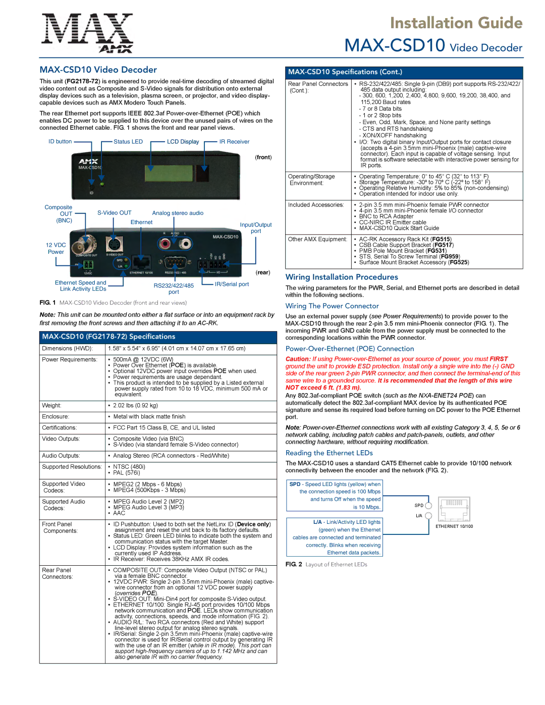
SPD - Speed LED lights (yellow) when the connection speed is 100 Mbps and turns Off when the speed is 10 Mbps.
L/A - Link/Activity LED lights (green) when the Ethernet cables are connected and terminated correctly. Blinks when receiving Ethernet data packets.
FIG. 2 Layout of Ethernet LEDs
SPD
L/A
ETHERNET 10/100