Wiring the MAX-CSD10 To Receive Streamed Media Content
The rear connectors are used to take an incoming media stream and then output it as a video signal (with audio). FIG. 3 shows a sample wiring configuration where a
the content to its connected media device.
Assigning a Static IP Address To The Unit Via The
Although the initial communication to the unit is done via a DHCP connection and since this is your stream source, it is recommended that you assign a Static IP Address to the unit via the
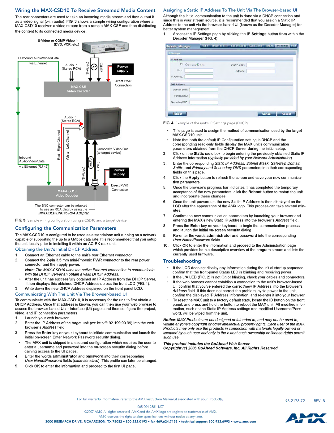
1. | Access the IP Settings page by clicking the IP Settings button from within the |
| Decoder Manager (FIG. 4). |
|
|
| (DVD, VCR, etc.) |
|
|
| |||
| Outbound Audio/Video/Data |
|
|
| |||||
|
|
|
| ||||||
|
|
|
| ||||||
| via Ethernet |
|
|
|
|
| (BNC) | ||
|
|
|
| Audio In | or |
| |||
|
|
|
| (Stereo RCA) |
| ||||
|
|
|
|
|
|
| |||
|
|
|
|
|
|
|
|
|
|
|
|
|
|
|
|
|
|
| |
|
|
|
|
|
|
|
|
| |
|
|
|
| Video Encoder |
|
|
| ||
|
|
|
|
|
|
|
|
|
|
Audio In
(Stereo RCA)
Power supply
Direct PWR Connection
FIG. 4 Example of the unit’s IP Settings page (DHCP)
|
|
| Right Channel |
|
|
|
|
|
|
|
|
|
|
|
|
|
|
| - Left Channel |
|
|
|
| ||||||
|
|
|
|
|
| Composite Video Out | ||||||||
|
|
| Red- |
| White | and/or | (to target device) | |||||||
Inbound |
| (BNC) |
|
|
| |||||||||
Audio/Video/Data |
|
|
|
|
|
|
|
|
|
|
|
| ||
|
|
|
|
|
|
|
|
|
|
|
|
| ||
via Ethernet |
|
|
|
|
|
|
|
|
|
|
|
| ||
|
|
|
|
|
|
|
|
|
|
|
|
|
| Power |
|
|
|
|
|
|
|
|
|
|
|
|
|
| supply |
|
|
|
|
|
|
|
|
|
|
|
|
|
|
|
|
|
|
|
|
|
|
|
|
|
|
|
|
| Direct PWR |
|
|
|
|
|
|
|
|
|
|
|
|
|
| |
|
|
|
|
|
|
|
|
| Connection | |||||
|
|
|
|
|
|
|
|
|
| |||||
|
|
| Video Decoder |
|
|
|
|
|
|
| ||||
|
|
|
|
|
|
|
|
|
|
|
|
|
|
|
The BNC connector can be adapted to use an RCA plug by using the
INCLUDED BNC to RCA Adapter.
FIG. 3 Sample wiring configuration using a CSD10 and a target device
Configuring the Communication Parameters
The
Obtaining the Unit’s Initial DHCP Address
1.Connect an Ethernet cable to the unit’s rear Ethernet connector.
2.Connect the
Note: The
•After the unit has successfully obtained an IP Address from the DHCP Server, it then displays this obtained DHCP Address across the front LCD (FIG. 1).
3.Write down the new DHCP Address displayed on the front panel LCD.
Communicating With The Unit Via The Browser-based UI
To communicate with the
1.Launch your web browser.
2.Enter the IP Address of the target unit (ex: http://192.199.99.99) into the web browser’s Address field.
3.Press the Enter key on your keyboard to initiate communication and launch the initial
•The MAX unit is shipped in a secured configuration which requires the user to enter a username and password into the
4.Enter the words administrator and password into their corresponding
User Name/Password fields
5.Click OK to enter the information and proceed to the first UI page.
•This page is used to assign the method of communication used by the target
•Note that both the default IP Configuration setting is DHCP and the corresponding
2.Click on the Static radio box to begin entering the previously obtained Static IP Address information (typically provided by your Network Administrator).
3.Enter the corresponding Static IP Address, Subnet Mask, Gateway, Domain Suffix, and Primary and Secondary DNS parameters into their corresponding fields on this page.
4.Click the Apply button to refresh the screen and save your new communica- tion parameters.
5.Once the browser’s progress bar indicates it has completed the temporary acceptance of the new parameters, click the Reboot button to restart the unit and incorporate these changes.
6.Once the unit
7.Confirm the new communication parameters by launching your browser and entering the MAX’s new Static IP Address into the browser’s Address field.
8.Press the Enter key on your keyboard to begin the communication process and launch the initial
9.
10.Click OK to enter the information and proceed to the Administration page which provides both a descriptive overview of the program stream and lists the currently used firmware.
Troubleshooting
•If the LCD does not display any information during the initial startup sequence, confirm that the
•If the L/A LED (FIG. 2) is not On or blinking, check your cables and connectors.
•If the web browser cannot establish a connection to the unit’s
•To reset the MAX unit to a factory default state, locate the ID button on the front panel, and press and hold the button to reboot the MAX unit. All modified infor- mation, such as the Static IP Address settings and modified Username/Pass- word, will be wiped from the unit.
Notice: MAX Products are not designed or intended to, and may not be used to, violate anyone’s copyright or other intellectual property rights. Each user of the MAX Products may only use the products in connection with materials legally owned or licensed by such user and only to the extent such ownership or license rights permit such use.
This product includes the GoAhead Web Server.
Copyright (c) 2006 GoAhead Software, Inc. All Rights Reserved.
For full warranty information, refer to the AMX Instruction Manual(s) associated with your Product(s). |
| REV: B |
|
©2007 AMX. All rights reserved. AMX and the AMX logo are registered trademarks of AMX.
AMX reserves the right to alter specifications without notice at any time.
3000 RESEARCH DRIVE, RICHARDSON, TX 75082 • 800.222.0193 • fax 469.624.7153 • technical support 800.932.6993 • www.amx.com