Wiring guidelines
Metreau keypads require 12 VDC power to operate properly. The necessary power is supplied via the AxLink or SWT cable. The maximum wiring distance is determined by power consumption, supplied voltage, and the wire gauge used for the cable. The following table lists wire sizes and the maximum lengths allowable based on the maximum power consumption rating of 170 mA.
AxLink Wiring Guidelines at 170 mA
Wire Size | Maximum Wiring Length |
|
|
18 AWG | 690.42 feet (210.43 m) |
|
|
20 AWG | 436.80 feet (133.13 m) |
|
|
22 AWG | 272.33 feet (83.00 m) |
|
|
24 AWG | 171.66 feet (52.32 m) |
|
|
The maximum wiring lengths for using AxLink power are based on a minimum of
13.5volts available. If the distance is greater than what is listed in the table, consult the Metreau Keypads Operation/Reference Guide for wiring with external power sources.
AxLink Data and Power Connections
Connect the control system's AxLink connector to the AxLink connector on the rear panel of the Metreau Keypad for data and 12 VDC power as shown in FIG. 4.
PWR + |
|
|
|
|
|
|
|
|
|
| PWR + |
|
|
|
|
|
|
|
|
|
| ||
AXP |
|
|
|
|
|
|
|
|
|
| AXP |
|
|
|
|
|
|
|
|
|
| ||
AXM |
|
|
|
|
|
|
|
|
|
| AXM |
|
|
|
|
|
|
|
|
|
| ||
GND - |
|
|
|
|
|
|
|
|
|
| GND - |
|
|
|
|
|
|
|
|
|
|
|
|
Metreau Keypad | Control System | ||||||||||
FIG. 4 AxLink |
|
|
|
|
|
| |||||
Using AxLink for Data with an Auxiliary Power Supply
Use an auxiliary 12 VDC power supply when the distance between the controller and server exceeds the limits described in the Wiring guidelines section. Connect only the GND
Connect the NetLinx Controller’s AxLink connector to the AxLink connector on the rear panel of the Metreau keypad, as shown in FIG. 5.
12 VDC power supply PWR (+) ![]() GND
GND
PWR + |
|
|
|
|
|
|
|
| PWR + | |
|
|
|
|
|
|
|
|
| ||
AXP |
|
|
|
|
|
|
|
|
| AXP |
|
|
|
|
|
|
|
| |||
AXM |
|
|
|
|
|
|
|
|
| AXM |
GND - |
|
|
|
|
|
|
|
|
| GND - |
|
|
|
|
|
|
| ||||
NetLinx Controller | Metreau keypad | |||||||||
FIG. 5 AxLink and 12 VDC power supply wiring diagram
Note: If you are not using power from AxLink, disconnect the wiring from the controller before wiring the Metreau keypad. Make sure the auxiliary power supply’s PWR (+) is not connected to the controller’s AxLink connector.
AxLink Status LED
The AxLink Status LED (located next to the AxLink connector), lights to indicate AxLink power/data status (see Operation / Reference Guide for details).
If the LED is on and not flashing, disconnect the AxLink connector and recheck all AxLink connections. Then, reconnect the AxLink connector to the panel and verify the LED is flashing once per second.
Mounting Procedures
AMX recommends mounting Metreau keypads in standard
•Conduit box should meet NEC specs (section 370)
•Minimum internal clearance of (HWD)
Note: Before touching the device, discharge the static electricity from your body by touching a grounded metal object.
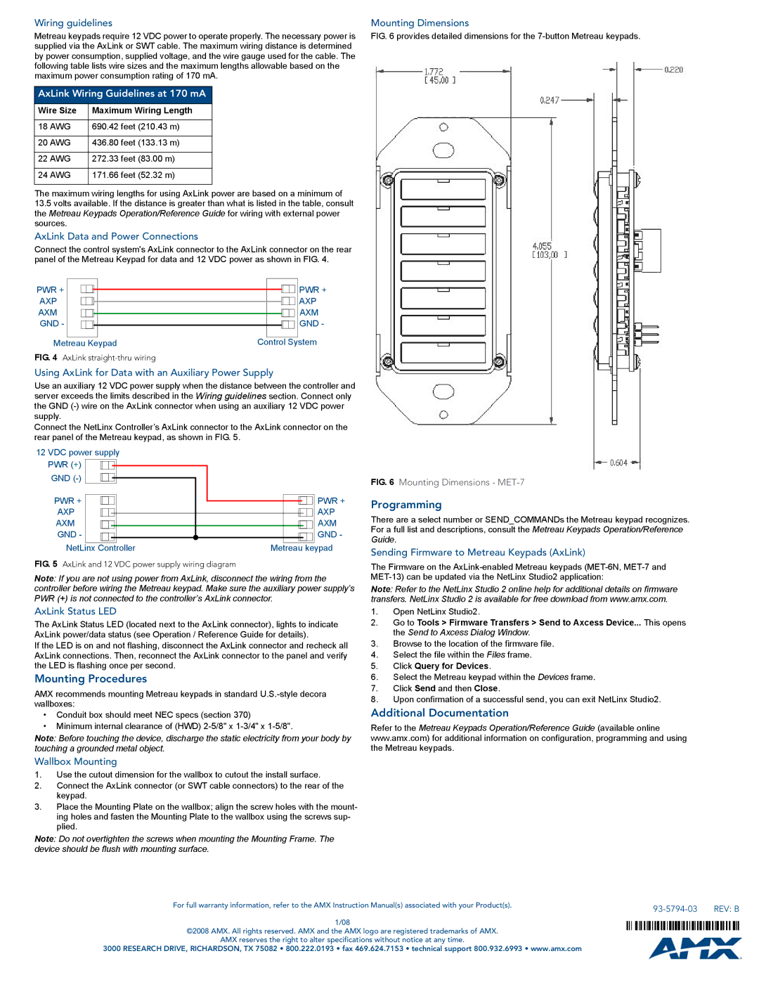
Mounting Dimensions
FIG. 6 provides detailed dimensions for the 7-button Metreau keypads.
FIG. 6 Mounting Dimensions - MET-7
Programming
There are a select number or SEND_COMMANDs the Metreau keypad recognizes. For a full list and descriptions, consult the Metreau Keypads Operation/Reference Guide.
Sending Firmware to Metreau Keypads (AxLink)
The Firmware on the
Note: Refer to the NetLinx Studio 2 online help for additional details on firmware transfers. NetLinx Studio 2 is available for free download from www.amx.com.
1.Open NetLinx Studio2.
2.Go to Tools > Firmware Transfers > Send to Axcess Device... This opens the Send to Axcess Dialog Window.
3.Browse to the location of the firmware file.
4.Select the file within the Files frame.
5.Click Query for Devices.
6.Select the Metreau keypad within the Devices frame.
7.Click Send and then Close.
8.Upon confirmation of a successful send, you can exit NetLinx Studio2.
Additional Documentation
Refer to the Metreau Keypads Operation/Reference Guide (available online www.amx.com) for additional information on configuration, programming and using the Metreau keypads.
Wallbox Mounting
1.Use the cutout dimension for the wallbox to cutout the install surface.
2.Connect the AxLink connector (or SWT cable connectors) to the rear of the keypad.
3.Place the Mounting Plate on the wallbox; align the screw holes with the mount- ing holes and fasten the Mounting Plate to the wallbox using the screws sup- plied.
Note: Do not overtighten the screws when mounting the Mounting Frame. The device should be flush with mounting surface.
For full warranty information, refer to the AMX Instruction Manual(s) associated with your Product(s). |
| REV: B |
|
1/08
©2008 AMX. All rights reserved. AMX and the AMX logo are registered trademarks of AMX.
AMX reserves the right to alter specifications without notice at any time.
3000 RESEARCH DRIVE, RICHARDSON, TX 75082 • 800.222.0193 • fax 469.624.7153 • technical support 800.932.6993 • www.amx.com