Installation Guide
Overview
The
![]()
![]() OLED display
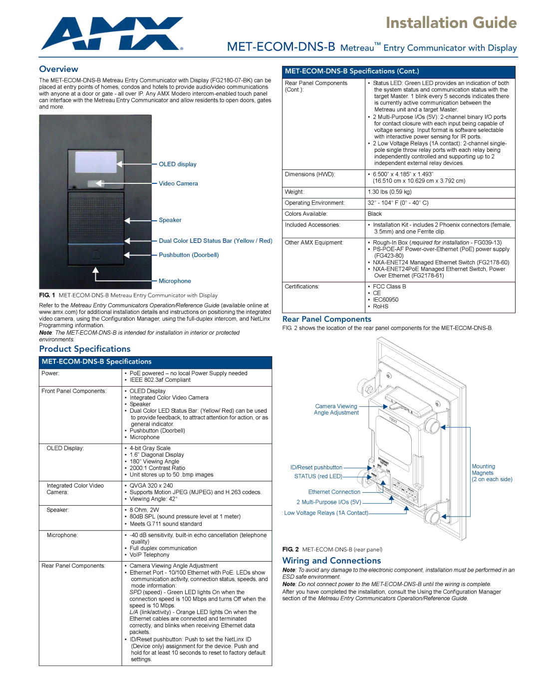
OLED display
Video Camera
![]()
![]() Speaker
Speaker
![]()
![]() Dual Color LED Status Bar (Yellow / Red)
Dual Color LED Status Bar (Yellow / Red)
![]()
![]()
![]() Pushbutton (Doorbell)
Pushbutton (Doorbell)
Microphone
FIG. 1 MET-ECOM-DNS-B Metreau Entry Communicator with Display
Refer to the Metreau Entry Communicators Operation/Reference Guide (available online at www.amx.com) for additional installation details and instructions on positioning the integrated video camera, using the Configuration Manager, using the
Note: The
MET-ECOM-DNS-B Specifications (Cont.)
Rear Panel Components | • | Status LED: Green LED provides an indication of both |
(Cont.): |
| the system status and communication status with the |
|
| target Master. 1 blink every 5 seconds indicates there |
|
| is currently active communication between the |
|
| Metreau unit and a target Master. |
| • | 2 |
|
| for contact closure with each input being capable of |
|
| voltage sensing. Input format is software selectable |
|
| with interactive power sensing for IR ports. |
| • | 2 Low Voltage Relays (1A contact): |
|
| pole single throw relay ports with each relay being |
|
| independently controlled and supporting up to 2 |
|
| independent external relay devices. |
|
|
|
Dimensions (HWD): | • | 6.500” x 4.185” x 1.493” |
|
| (16.510 cm x 10.629 cm x 3.792 cm) |
|
| |
Weight: | 1.30 lbs (0.59 kg) | |
|
| |
Operating Environment: | 32° - 104° F (0° - 40° C) | |
|
| |
Colors Available: | Black | |
|
| |
Included Accessories: | • Installation Kit - includes 2 Phoenix connectors (female, | |
|
| 3.5mm) and one Ferrite clip. |
|
|
|
Other AMX Equipment: | • |
|
| • | |
|
| |
| • | |
| • | |
|
| Over Ethernet |
|
|
|
Certifications: | • | FCC Class B |
| • CE | |
| • IEC60950 | |
| • RoHS | |
|
|
|
Rear Panel Components
FIG. 2 shows the location of the rear panel components for the MET-ECOM-DNS-B.
Product Specifications
Power: | • PoE powered – no local Power Supply needed | |
| • | IEEE 802.3af Compliant |
|
|
|
Front Panel Components: | • | OLED Display |
| • | Integrated Color Video Camera |
| • | Speaker |
| • | Dual Color LED Status Bar: (Yellow/ Red) can be used |
|
| to provide feedback, to attract attention for action, or as |
|
| general indicator. |
| • | Pushbutton (Doorbell) |
| • | Microphone |
|
|
|
OLED Display: | • | |
| • | 1.6” Diagonal Display |
| • | 180° Viewing Angle |
| • | 2000:1 Contrast Ratio |
| • | Unit stores up to 50 .bmp images |
|
|
|
Integrated Color Video | • | QVGA 320 x 240 |
Camera: | • Supports Motion JPEG (MJPEG) and H.263 codecs. | |
| • | Viewing Angle: 42° |
|
| |
Speaker: | • 8 Ohm, 2W | |
| • | 80dB SPL (sound pressure level at 1 meter) |
| • | Meets G.711 sound standard |
|
|
|
Microphone: | • | |
|
| quality) |
| • | Full duplex communication |
| • | VoIP Telephony |
Camera Viewing ![]()
![]()
Angle Adjustment
ID/Reset pushbutton ![]()
![]() STATUS (red LED)
STATUS (red LED)![]()
![]()
Ethernet Connection ![]() 2
2 ![]()
Low Voltage Relays (1A Contact)![]()
FIG. 2 MET-ECOM-DNS-B (rear panel)
Mounting
Magnets
(2 on each side)
Rear Panel Components: | • | Camera Viewing Angle Adjustment |
| • | Ethernet Port - 10/100 Ethernet with PoE. LEDs show |
|
| communication activity, connection status, speeds, and |
|
| mode information: |
|
| SPD (speed) - Green LED lights On when the |
|
| connection speed is 100 Mbps and turns Off when the |
|
| speed is 10 Mbps. |
|
| L/A (link/activity) - Orange LED lights On when the |
|
| Ethernet cables are connected and terminated |
|
| correctly, and blinks when receiving Ethernet data |
|
| packets. |
| • | ID/Reset pushbutton: Push to set the NetLinx ID |
|
| (Device only) assignment for the device. Push and |
|
| hold for at least 10 seconds to reset to factory default |
|
| settings. |
Wiring and Connections
Note: To avoid any damage to the electronic component, installation must be performed in an ESD safe environment.
Note: Do not connect power to the
After you have completed the installation, consult the Using the Configuration Manager section of the Metreau Entry Communicators Operation/Reference Guide.