Installation Guide
NXC-I/O10 Input/Output Control Card
NetLinx Control Cards and NetModules
NetLinx Control Cards can be installed in either the NXF CardFrame,
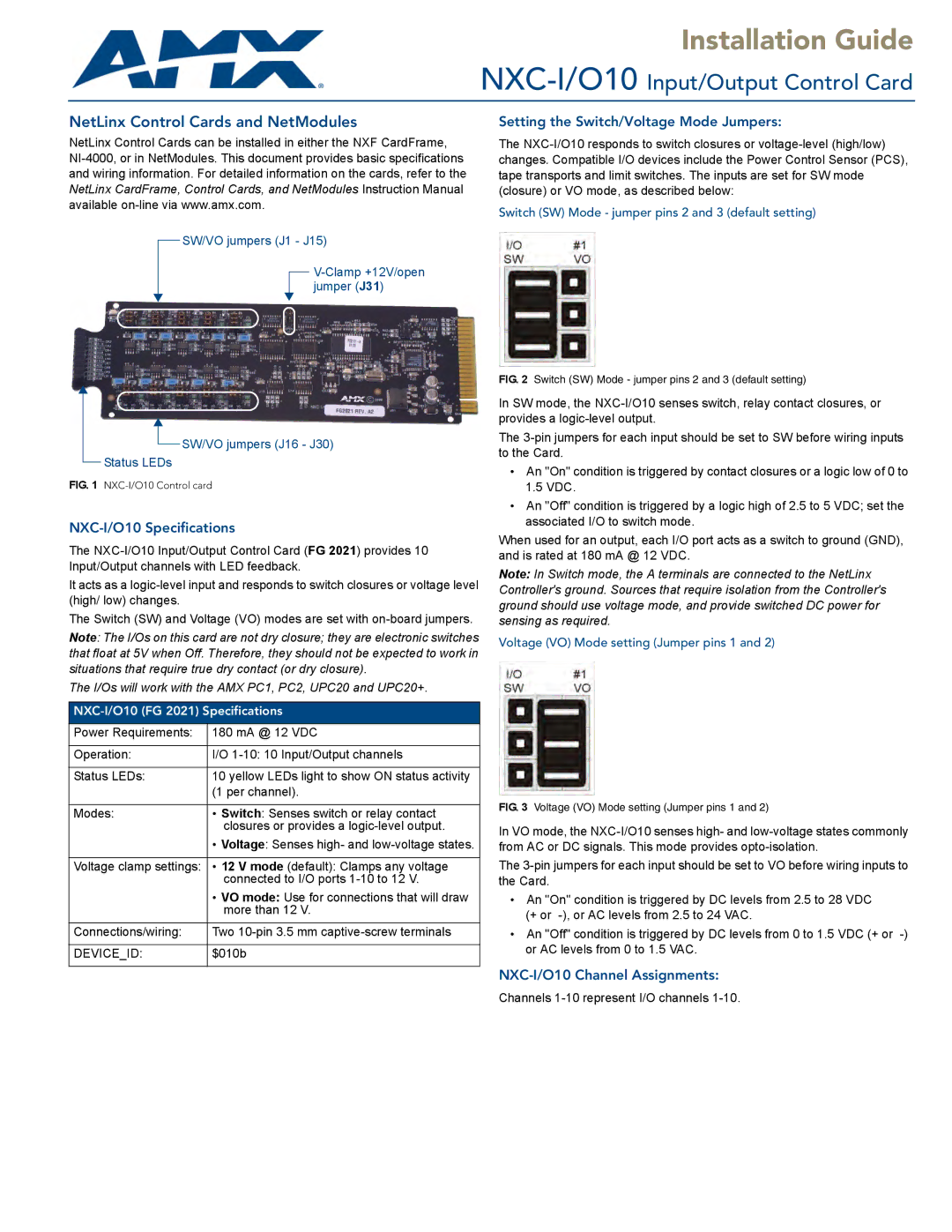
SW/VO jumpers (J1 - J15)
Setting the Switch/Voltage Mode Jumpers:
The
Switch (SW) Mode - jumper pins 2 and 3 (default setting)
![]() SW/VO jumpers (J16 - J30)
SW/VO jumpers (J16 - J30)
Status LEDs
FIG. 1 NXC-I/O10 Control card
NXC-I/O10 Specifications
The
It acts as a
The Switch (SW) and Voltage (VO) modes are set with
Note: The I/Os on this card are not dry closure; they are electronic switches that float at 5V when Off. Therefore, they should not be expected to work in situations that require true dry contact (or dry closure).
The I/Os will work with the AMX PC1, PC2, UPC20 and UPC20+.
NXC-I/O10 (FG 2021) Specifications
Power Requirements: | 180 mA @ 12 VDC |
|
|
Operation: | I/O |
|
|
Status LEDs: | 10 yellow LEDs light to show ON status activity |
| (1 per channel). |
|
|
Modes: | • Switch: Senses switch or relay contact |
| closures or provides a |
| • Voltage: Senses high- and |
|
|
Voltage clamp settings: | • 12 V mode (default): Clamps any voltage |
| connected to I/O ports |
| • VO mode: Use for connections that will draw |
| more than 12 V. |
|
|
Connections/wiring: | Two |
|
|
DEVICE_ID: | $010b |
|
|
FIG. 2 Switch (SW) Mode - jumper pins 2 and 3 (default setting)
In SW mode, the
The
•An "On" condition is triggered by contact closures or a logic low of 0 to 1.5 VDC.
•An "Off" condition is triggered by a logic high of 2.5 to 5 VDC; set the associated I/O to switch mode.
When used for an output, each I/O port acts as a switch to ground (GND), and is rated at 180 mA @ 12 VDC.
Note: In Switch mode, the A terminals are connected to the NetLinx Controller's ground. Sources that require isolation from the Controller's ground should use voltage mode, and provide switched DC power for sensing as required.
Voltage (VO) Mode setting (Jumper pins 1 and 2)
FIG. 3 Voltage (VO) Mode setting (Jumper pins 1 and 2)
In VO mode, the
The
•An "On" condition is triggered by DC levels from 2.5 to 28 VDC (+ or
•An "Off" condition is triggered by DC levels from 0 to 1.5 VDC (+ or
NXC-I/O10 Channel Assignments:
Channels