Pinouts, Signals, and I/O Mode Functions:
NXC-I/O10 Pinouts, Signals, and I/O Mode Functions
Pin | Signal | SW mode Functions | VO mode functions |
|
|
|
|
1 | Common | Signal ground | Common #1 |
|
|
|
|
2 | I/O #1 | Input #1 | Input #1 |
|
|
|
|
3 | Common | Signal ground | Common #2 |
|
|
|
|
4 | I/O #2 | Input #2 | Input #2 |
|
|
|
|
5 | Common | Signal ground | Common #3 |
|
|
|
|
6 | I/O #3 | Input #3 | Input #3 |
|
|
|
|
7 | Common | Signal ground | Common #4 |
|
|
|
|
8 | I/O #4 | Input #4 | Input #4 |
|
|
|
|
9 | Common | Signal ground | Common #5 |
|
|
|
|
10 | I/O #5 | Input #5 | Input #5 |
|
|
|
|
11 | Common | Signal ground | Common #6 |
|
|
|
|
12 | I/O #6 | Input #6 | Input #6 |
|
|
|
|
13 | Common | Signal ground | Common #7 |
|
|
|
|
14 | I/O #7 | Input #7 | Input #7 |
|
|
|
|
15 | Common | Signal ground | Common #8 |
|
|
|
|
16 | I/O #8 | Input #8 | Input #8 |
|
|
|
|
17 | Common | Signal ground | Common #9 |
|
|
|
|
18 | I/O #9 | Input #9 | Input #9 |
|
|
|
|
19 | Common | Signal ground | Common #10 |
|
|
|
|
20 | I/O #10 | Input #10 | Input #10 |
|
|
|
|
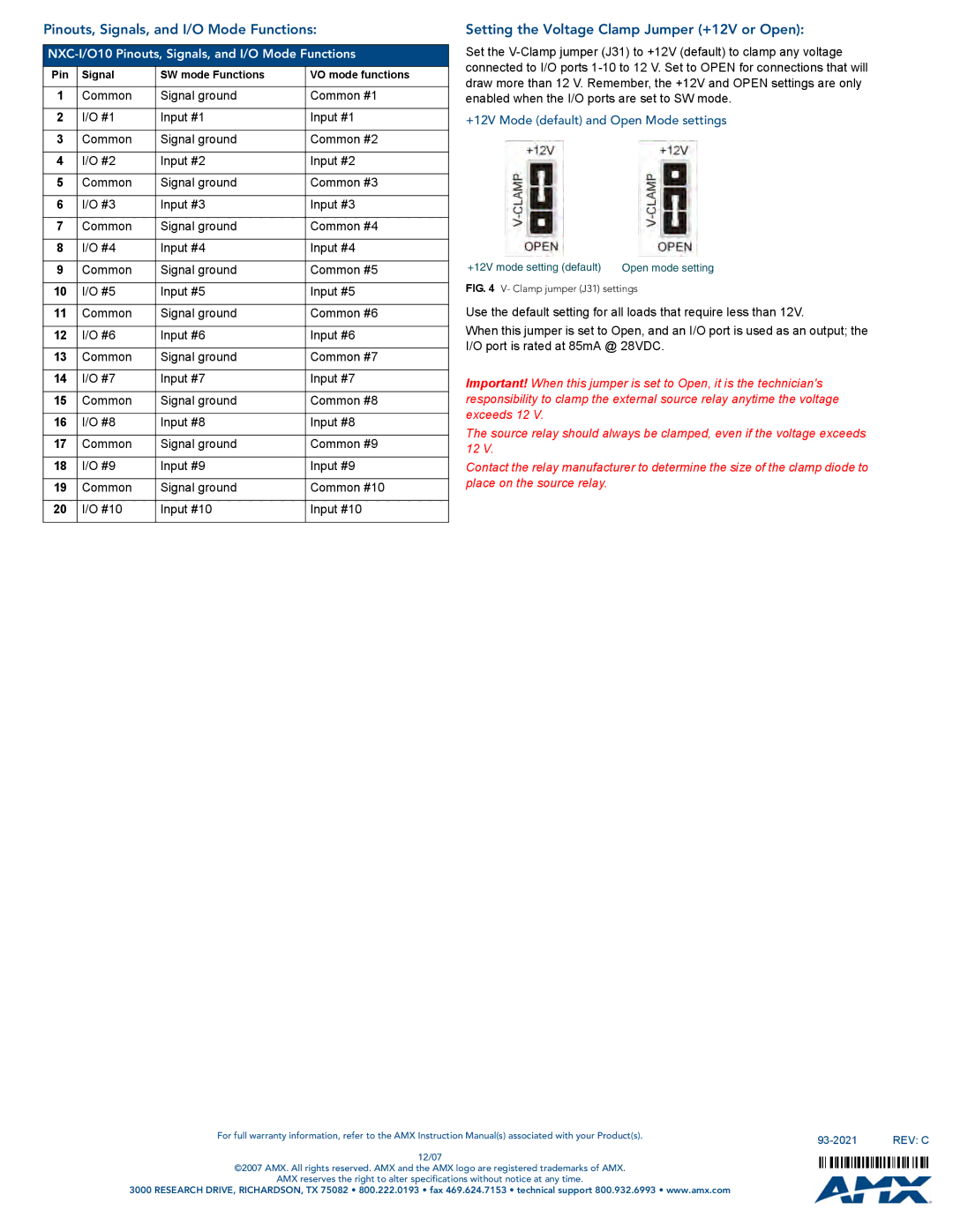
Setting the Voltage Clamp Jumper (+12V or Open):
Set the
+12V Mode (default) and Open Mode settings
+12V mode setting (default) | Open mode setting |
FIG. 4 V- Clamp jumper (J31) settings
Use the default setting for all loads that require less than 12V.
When this jumper is set to Open, and an I/O port is used as an output; the I/O port is rated at 85mA @ 28VDC.
Important! When this jumper is set to Open, it is the technician's responsibility to clamp the external source relay anytime the voltage exceeds 12 V.
The source relay should always be clamped, even if the voltage exceeds 12 V.
Contact the relay manufacturer to determine the size of the clamp diode to place on the source relay.
For full warranty information, refer to the AMX Instruction Manual(s) associated with your Product(s). |
| REV: C |
|
12/07
©2007 AMX. All rights reserved. AMX and the AMX logo are registered trademarks of AMX.
AMX reserves the right to alter specifications without notice at any time.
3000 RESEARCH DRIVE, RICHARDSON, TX 75082 • 800.222.0193 • fax 469.624.7153 • technical support 800.932.6993 • www.amx.com