Quick Start Guide
NXC-ME260-64 NetLinx Master Card
For more detailed installation, configuration, programming, file transfer, and operating instructions, refer to the
Overview
The NetLinx
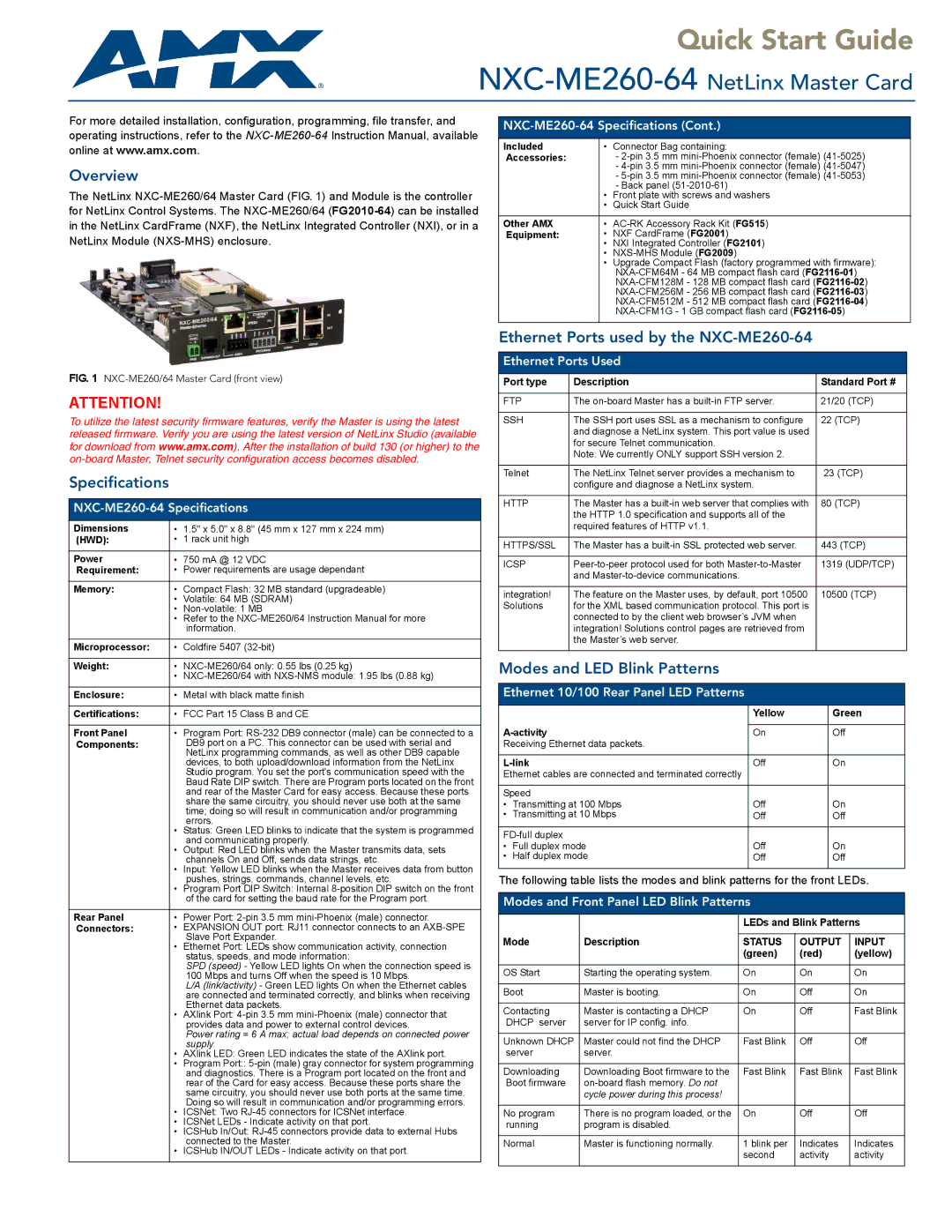
FIG. 1 NXC-ME260/64 Master Card (front view)
ATTENTION!
To utilize the latest security firmware features, verify the Master is using the latest released firmware. Verify you are using the latest version of NetLinx Studio (available for download from www.amx.com). After the installation of build 130 (or higher) to the
Specifications
NXC-ME260-64 Specifications
Dimensions | • | 1.5" x 5.0" x 8.8" (45 mm x 127 mm x 224 mm) |
(HWD): | • | 1 rack unit high |
|
| |
Power | • 750 mA @ 12 VDC | |
Requirement: | • | Power requirements are usage dependant |
|
|
|
Memory: | • | Compact Flash: 32 MB standard (upgradeable) |
| • | Volatile: 64 MB (SDRAM) |
| • | |
| • | Refer to the |
|
| information. |
|
|
|
Microprocessor: | • | Coldfire 5407 |
|
|
|
Weight: | • | |
| • | |
|
|
|
Enclosure: | • | Metal with black matte finish |
|
|
|
Certifications: | • | FCC Part 15 Class B and CE |
|
|
|
Front Panel | • | Program Port: |
Components: |
| DB9 port on a PC. This connector can be used with serial and |
|
| NetLinx programming commands, as well as other DB9 capable |
|
| devices, to both upload/download information from the NetLinx |
|
| Studio program. You set the port's communication speed with the |
|
| Baud Rate DIP switch. There are Program ports located on the front |
|
| and rear of the Master Card for easy access. Because these ports |
|
| share the same circuitry, you should never use both at the same |
|
| time; doing so will result in communication and/or programming |
| • | errors. |
| Status: Green LED blinks to indicate that the system is programmed | |
| • | and communicating properly. |
| Output: Red LED blinks when the Master transmits data, sets | |
| • | channels On and Off, sends data strings, etc. |
| Input: Yellow LED blinks when the Master receives data from button | |
| • | pushes, strings, commands, channel levels, etc. |
| Program Port DIP Switch: Internal | |
|
| of the card for setting the baud rate for the Program port. |
|
|
|
Rear Panel | • | Power Port: |
Connectors: | • | EXPANSION OUT port: RJ11 connector connects to an |
| • | Slave Port Expander. |
| Ethernet Port: LEDs show communication activity, connection | |
|
| status, speeds, and mode information: |
|
| SPD (speed) - Yellow LED lights On when the connection speed is |
|
| 100 Mbps and turns Off when the speed is 10 Mbps. |
|
| L/A (link/activity) - Green LED lights On when the Ethernet cables |
|
| are connected and terminated correctly, and blinks when receiving |
| • | Ethernet data packets. |
| AXlink Port: | |
|
| provides data and power to external control devices. |
|
| Power rating = 6 A max; actual load depends on connected power |
| • | supply. |
| AXlink LED: Green LED indicates the state of the AXlink port. | |
| • | Program Port:: |
|
| and diagnostics. There is a Program port located on the front and |
|
| rear of the Card for easy access. Because these ports share the |
|
| same circuitry, you should never use both ports at the same time. |
| • | Doing so will result in communication and/or programming errors. |
| ICSNet: Two | |
| • | ICSNet LEDs - Indicate activity on that port. |
| • | ICSHub In/Out: |
| • | connected to the Master. |
| ICSHub IN/OUT LEDs - Indicate activity on that port. | |
|
|
|
|
|
|
Included | • | Connector Bag containing: |
Accessories: |
| - |
|
| - |
|
| - |
| • | - Back panel |
| Front plate with screws and washers | |
| • | Quick Start Guide |
|
|
|
Other AMX | • | |
Equipment: | • | NXF CardFrame (FG2001) |
| • | NXI Integrated Controller (FG2101) |
| • | |
| • | Upgrade Compact Flash (factory programmed with firmware): |
|
| |
|
| |
|
| |
|
| |
|
| |
|
|
|
Ethernet Ports used by the NXC-ME260-64
Ethernet Ports Used
Port type | Description | Standard Port # |
|
|
|
FTP | The | 21/20 (TCP) |
|
|
|
SSH | The SSH port uses SSL as a mechanism to configure | 22 (TCP) |
| and diagnose a NetLinx system. This port value is used |
|
| for secure Telnet communication. |
|
| Note: We currently ONLY support SSH version 2. |
|
|
|
|
Telnet | The NetLinx Telnet server provides a mechanism to | 23 (TCP) |
| configure and diagnose a NetLinx system. |
|
|
|
|
HTTP | The Master has a | 80 (TCP) |
| the HTTP 1.0 specification and supports all of the |
|
| required features of HTTP v1.1. |
|
|
|
|
HTTPS/SSL | The Master has a | 443 (TCP) |
|
|
|
ICSP | 1319 (UDP/TCP) | |
| and |
|
|
|
|
integration! | The feature on the Master uses, by default, port 10500 | 10500 (TCP) |
Solutions | for the XML based communication protocol. This port is |
|
| connected to by the client web browser’s JVM when |
|
| integration! Solutions control pages are retrieved from |
|
| the Master’s web server. |
|
|
|
|
Modes and LED Blink Patterns
Ethernet 10/100 Rear Panel LED Patterns
|
| Yellow | Green |
|
|
| |
On | Off | ||
Receiving Ethernet data packets. |
|
| |
|
|
| |
| Off | On | |
Ethernet cables are connected and terminated correctly |
|
| |
|
|
| |
Speed |
|
| |
• Transmitting at 100 Mbps | Off | On | |
• Transmitting at 10 Mbps | Off | Off | |
|
|
| |
|
| ||
• | Full duplex mode | Off | On |
• | Half duplex mode | Off | Off |
|
|
|
|
The following table lists the modes and blink patterns for the front LEDs.
Modes and Front Panel LED Blink Patterns
|
| LEDs and Blink Patterns | ||
Mode | Description |
|
|
|
STATUS | OUTPUT | INPUT | ||
|
| (green) | (red) | (yellow) |
|
|
|
|
|
OS Start | Starting the operating system. | On | On | On |
|
|
|
|
|
Boot | Master is booting. | On | Off | On |
|
|
|
|
|
Contacting | Master is contacting a DHCP | On | Off | Fast Blink |
DHCP server | server for IP config. info. |
|
|
|
|
|
|
|
|
Unknown DHCP | Master could not find the DHCP | Fast Blink | Off | Off |
server | server. |
|
|
|
|
|
|
|
|
Downloading | Downloading Boot firmware to the | Fast Blink | Fast Blink | Fast Blink |
Boot firmware |
|
|
| |
| cycle power during this process! |
|
|
|
|
|
|
|
|
No program | There is no program loaded, or the | On | Off | Off |
running | program is disabled. |
|
|
|
|
|
|
|
|
Normal | Master is functioning normally. | 1 blink per | Indicates | Indicates |
|
| second | activity | activity |
|
|
|
|
|