Quick Start Guide
NXS-NMS NetLinx NetModules
NetLinx Control Cards and NetModules
NetLinx Control Cards can be installed in the NXF CardFrame,
NetModules (NXS-NMS)
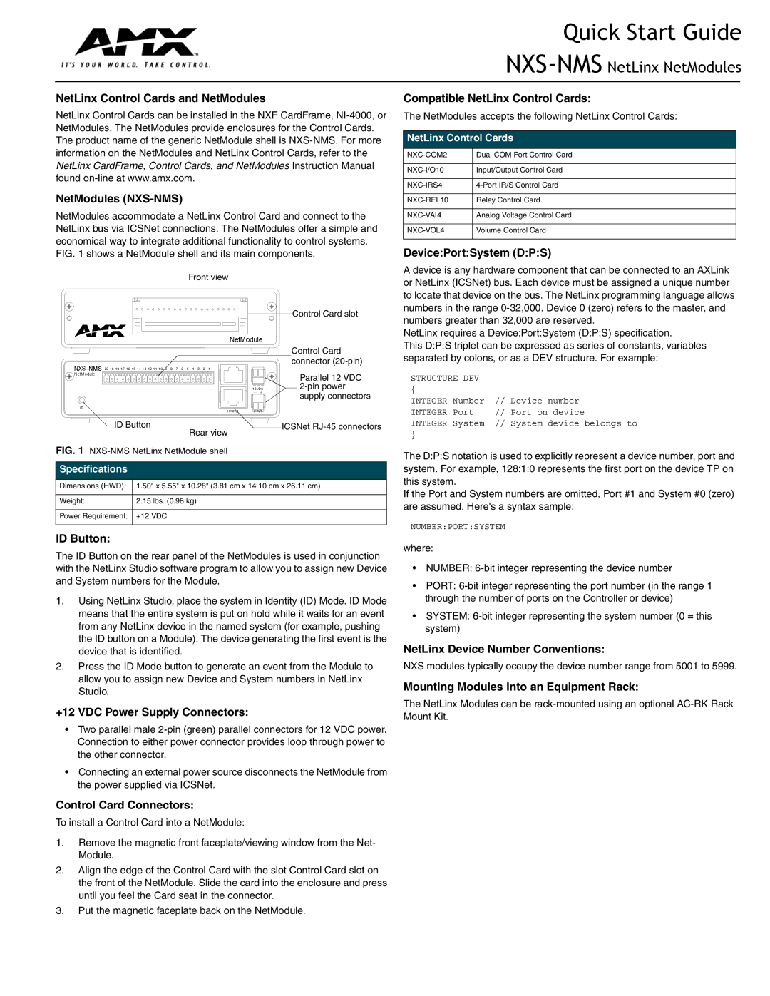
NetModules accommodate a NetLinx Control Card and connect to the NetLinx bus via ICSNet connections. The NetModules offer a simple and economical way to integrate additional functionality to control systems. FIG. 1 shows a NetModule shell and its main components.
Front view
Control Card slot
NetModule
|
|
| Control Card |
| connector | ||
|
| ||
NetModule |
|
| Parallel 12 VDC |
|
|
| |
|
| 12VDC | |
|
|
| supply connectors |
ID | ICSNet | PWR |
|
|
| ||
ID Button |
| ICSNet | |
| Rear view |
|
|
FIG. 1 |
|
| |
Specifications |
|
|
|
Dimensions (HWD): | 1.50" x 5.55" x 10.28" (3.81 cm x 14.10 cm x 26.11 cm) | ||
Weight: | 2.15 lbs. (0.98 kg) |
|
|
Power Requirement: | +12 VDC |
|
|
Compatible NetLinx Control Cards:
The NetModules accepts the following NetLinx Control Cards:
NetLinx Control Cards
Dual COM Port Control Card | |
|
|
Input/Output Control Card | |
|
|
|
|
Relay Control Card | |
|
|
Analog Voltage Control Card | |
|
|
Volume Control Card | |
|
|
Device:Port:System (D:P:S)
A device is any hardware component that can be connected to an AXLink or NetLinx (ICSNet) bus. Each device must be assigned a unique number to locate that device on the bus. The NetLinx programming language allows numbers in the range
NetLinx requires a Device:Port:System (D:P:S) specification.
This D:P:S triplet can be expressed as series of constants, variables separated by colons, or as a DEV structure. For example:
STRUCTURE DEV
{
INTEGER Number // Device number
INTEGER Port // Port on device
INTEGER System // System device belongs to
}
The D:P:S notation is used to explicitly represent a device number, port and system. For example, 128:1:0 represents the first port on the device TP on this system.
If the Port and System numbers are omitted, Port #1 and System #0 (zero) are assumed. Here's a syntax sample:
NUMBER:PORT:SYSTEM
ID Button:
The ID Button on the rear panel of the NetModules is used in conjunction with the NetLinx Studio software program to allow you to assign new Device and System numbers for the Module.
1.Using NetLinx Studio, place the system in Identity (ID) Mode. ID Mode means that the entire system is put on hold while it waits for an event from any NetLinx device in the named system (for example, pushing the ID button on a Module). The device generating the first event is the device that is identified.
2.Press the ID Mode button to generate an event from the Module to allow you to assign new Device and System numbers in NetLinx Studio.
+12 VDC Power Supply Connectors:
•Two parallel male
•Connecting an external power source disconnects the NetModule from the power supplied via ICSNet.
Control Card Connectors:
To install a Control Card into a NetModule:
1.Remove the magnetic front faceplate/viewing window from the Net- Module.
2.Align the edge of the Control Card with the slot Control Card slot on the front of the NetModule. Slide the card into the enclosure and press until you feel the Card seat in the connector.
3.Put the magnetic faceplate back on the NetModule.
where:
•NUMBER:
•PORT:
•SYSTEM:
NetLinx Device Number Conventions:
NXS modules typically occupy the device number range from 5001 to 5999.
Mounting Modules Into an Equipment Rack:
The NetLinx Modules can be