Panel Connectors
FIG. 2 shows the connectors located on the 1500VG Modero Multimedia touch panels.
|
| A | L |
|
|
|
|
|
|
| 12VDC |
|
|
RGB | AUDIO/VIDEO | ETHERNET | PWR |
| PROGRAM | |
Composite/RGB |
|
| Ethernet | Stereo | Keyboard/Mouse |
|
|
| Output | USB connectors | |||
and |
| (CAT5) |
| (2) | ||
| PWR | (Program | ||||
control |
|
|
|
| ||
(CAT 5) | from AVB/RGB | Port) | |
(CAT 5) | |||
| |||
|
|
FIG. 2 Connector layout on the 1500VG Touch Panels
NXA-AVB/RGB Breakout Box
FIG. 3 shows the front and rear connectors on the NXA-AVB/RGB breakout box. This breakout box can be mounted on either a horizontal flat surface or into an equipment rack (using an optional AC-RK Rack Kit).
Mic Out | Audio | Composite/ | RGB (to internal | |
In |
| |||
|
|
| ||
(rear) |
| Luma |
|
|
|
|
| (front) |
RGB/Component | USB | Power | Ethernet In | Power | Audio/Video | Ethernet | |
In | (to panel) | (to panel) | (to panel) | ||||
|
|
|
FIG. 3 Connector layouts on the NXA-AVB/RGB Breakout Box
Wiring the NXA-AVB/RGB Connectors and Cables
The inputs and outputs on the breakout box are separated into front and rear connectors. The rear connectors are used to input external signals. The front connectors are used to communicate signals between the
between the red, green, and blue video signals. Therefore, for longer cable runs, the video quality will be much higher using the Belden VideoTwist 7987 cable versus standard CAT5 (or other Ethernet compliant cables).
Wiring for Unbalanced Audio
Use FIG. 5 to configure an unbalanced audio connection.
GND |
| Unbalanced IN | |
IN- | Left Channel | ||
(Jumper IN- to GND) | |||
| |||
IN+ |
| ||
|
| ||
GND |
| Unbalanced IN | |
IN- | Right Channel | ||
(Jumper IN- to GND) | |||
IN+ |
| ||
|
| ||
AUDIO IN |
|
| |
MIC OUT |
|
| |
GND |
| Unbalanced OUT | |
OUT- | Microphone | ||
OUT+ |
|
|
FIG. 5 Wiring the rear AUDIO IN and MIC OUT for use with Unbalanced Audio
Wiring for Balanced Audio
Use FIG. 6 to configure a balanced audio connection.
GND |
|
|
|
| Ground signal |
|
|
|
|
| Return signal | Balanced OUT | |
OUT- |
|
|
|
| ||
|
|
|
| Line signal |
| |
OUT+ |
|
|
|
|
| |
|
|
|
|
|
|
|
FIG. 6 Wiring the rear AUDIO IN and MIC OUT for use with Balanced Audio
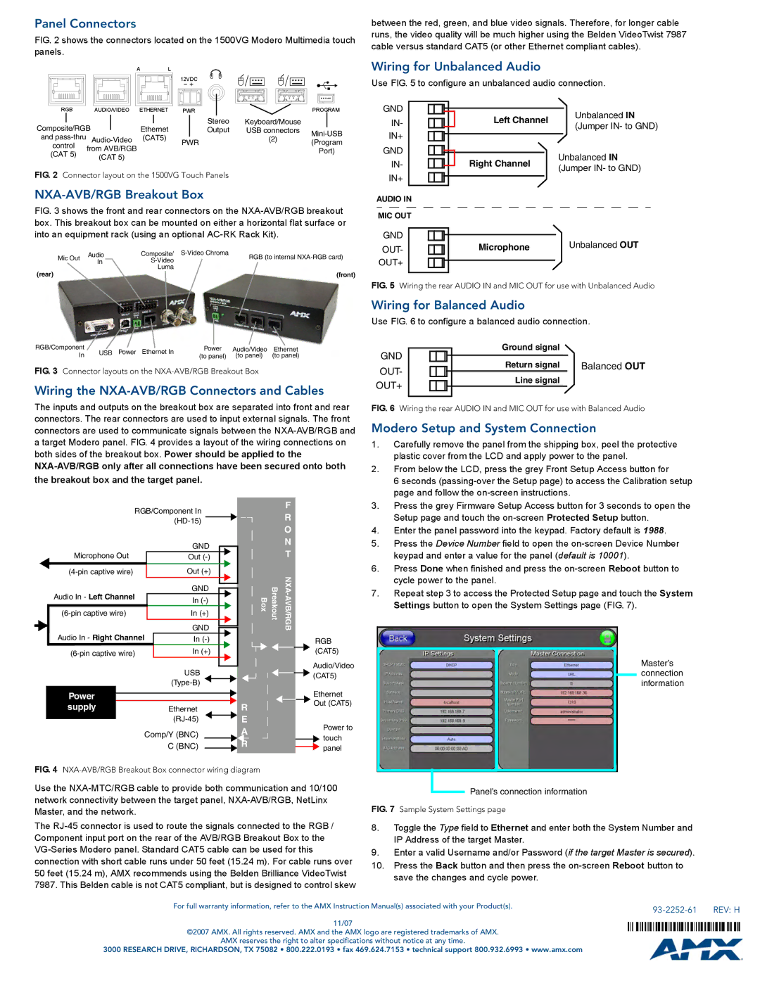
Modero Setup and System Connection
1. | Carefully remove the panel from the shipping box, peel the protective |
| plastic cover from the LCD and apply power to the panel. |
2. | From below the LCD, press the grey Front Setup Access button for |
| 6 seconds |
| page and follow the |
|
|
|
|
|
| RGB/Component In |
| ||||||||||
|
|
|
|
|
|
|
|
|
|
|
|
|
| ||||
|
|
|
|
| Microphone Out |
|
|
| GND |
|
|
| |||||
|
|
|
|
|
|
|
|
|
| ||||||||
|
|
|
|
|
|
| Out |
|
|
| |||||||
|
|
|
|
|
|
| Out (+) |
|
|
| |||||||
|
|
| Audio In - Left Channel |
|
| GND |
|
|
|
| |||||||
|
|
|
|
|
|
| |||||||||||
|
|
|
|
|
|
|
|
| |||||||||
|
|
|
|
| In |
|
|
|
| ||||||||
|
|
|
|
|
|
|
|
|
|
|
|
| |||||
|
|
|
| In (+) |
|
|
| ||||||||||
|
|
|
|
|
|
|
|
|
|
|
|
|
|
|
|
|
|
|
|
| Audio In - Right Channel |
| GND |
|
|
| |||||||||
|
|
|
|
|
|
|
| ||||||||||
|
|
|
| In |
|
|
| ||||||||||
|
|
|
|
| In (+) |
|
|
| |||||||||
|
|
|
|
|
|
|
|
|
|
|
|
|
| ||||
|
|
|
|
|
|
|
|
|
| USB |
| ||||||
|
|
|
|
|
|
|
|
|
|
|
|
|
| ||||
|
|
|
| Power |
|
|
|
|
|
|
|
|
|
|
|
| |
|
|
|
|
|
|
|
|
|
|
|
|
|
| ||||
|
|
|
| supply |
|
| Ethernet |
| |||||||||
|
|
|
|
|
|
|
|
|
|
|
|
|
| ||||
|
|
|
|
|
|
|
|
|
|
|
|
|
|
| |||
Comp/Y (BNC)
C (BNC)
|
| F |
|
| R |
|
| O |
|
| N |
|
| T |
Box | Breakout | |
|
| RGB |
|
| (CAT5) |
|
| Audio/Video |
|
| (CAT5) |
|
| Ethernet |
R |
| Out (CAT5) |
|
| |
E |
| Power to |
A |
| |
| touch | |
R |
| |
| panel | |
|
|
3. | Press the grey Firmware Setup Access button for 3 seconds to open the |
| Setup page and touch the |
4. | Enter the panel password into the keypad. Factory default is 1988. |
5. | Press the Device Number field to open the |
| keypad and enter a value for the panel (default is 10001). |
6. | Press Done when finished and press the |
| cycle power to the panel. |
7. | Repeat step 3 to access the Protected Setup page and touch the System |
| Settings button to open the System Settings page (FIG. 7). |
Master’s connection information
FIG. 4 NXA-AVB/RGB Breakout Box connector wiring diagram
Use the
The
Panel’s connection information
FIG. 7 Sample System Settings page
8.Toggle the Type field to Ethernet and enter both the System Number and IP Address of the target Master.
9.Enter a valid Username and/or Password (if the target Master is secured).
10.Press the Back button and then press the
For full warranty information, refer to the AMX Instruction Manual(s) associated with your Product(s). |
| REV: H |
|
11/07
©2007 AMX. All rights reserved. AMX and the AMX logo are registered trademarks of AMX.
AMX reserves the right to alter specifications without notice at any time.
3000 RESEARCH DRIVE, RICHARDSON, TX 75082 • 800.222.0193 • fax 469.624.7153 • technical support 800.932.6993 • www.amx.com