Quick Start Guide
Mio Modero® Prestige
Overview
The Mio Modero Prestige
You need KeypadBuilder to properly program these devices. The application and documentation are available from www.amx.com.
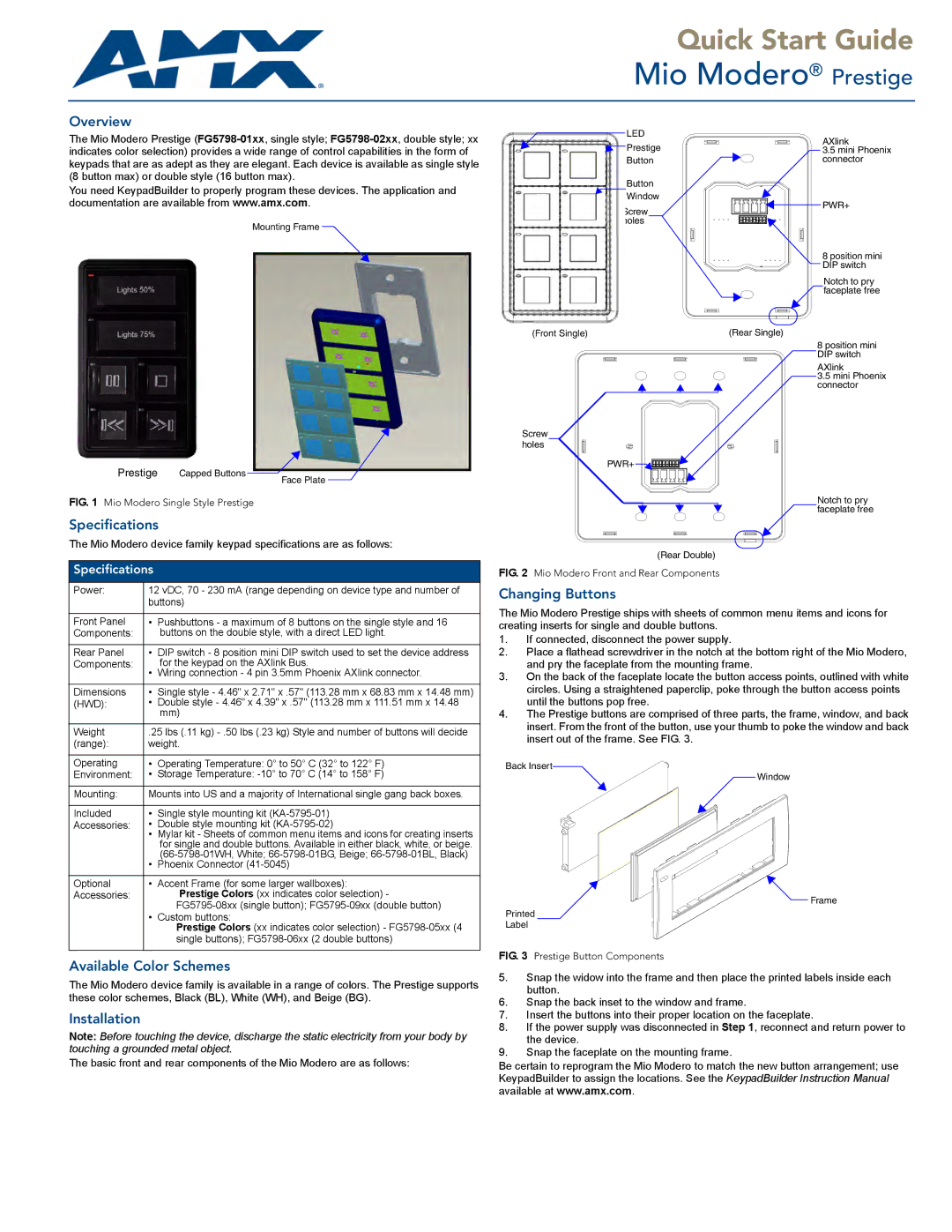
Mounting Frame
Prestige Capped Buttons ![]()
Face Plate
FIG. 1 Mio Modero Single Style Prestige
Specifications
The Mio Modero device family keypad specifications are as follows:
Specifications
Power: | 12 vDC, 70 - 230 mA (range depending on device type and number of | |
| buttons) | |
|
|
|
Front Panel | • | Pushbuttons - a maximum of 8 buttons on the single style and 16 |
Components: |
| buttons on the double style, with a direct LED light. |
|
|
|
Rear Panel | • | DIP switch - 8 position mini DIP switch used to set the device address |
Components: | • | for the keypad on the AXlink Bus. |
| Wiring connection - 4 pin 3.5mm Phoenix AXlink connector. | |
|
|
|
Dimensions | • | Single style - 4.46" x 2.71" x .57" (113.28 mm x 68.83 mm x 14.48 mm) |
(HWD): | • | Double style - 4.46" x 4.39" x .57" (113.28 mm x 111.51 mm x 14.48 |
|
| mm) |
|
| |
Weight | .25 lbs (.11 kg) | |
(range): | weight. | |
|
|
|
Operating | • | Operating Temperature: 0° to 50° C (32° to 122° F) |
Environment: | • | Storage Temperature: |
|
| |
Mounting: | Mounts into US and a majority of International single gang back boxes. | |
|
|
|
Included | • | Single style mounting kit |
Accessories: | • | Double style mounting kit |
| • | Mylar kit - Sheets of common menu items and icons for creating inserts |
|
| for single and double buttons. Available in either black, white, or beige. |
| • | |
| Phoenix Connector | |
|
|
|
Optional | • | Accent Frame (for some larger wallboxes): |
Accessories: |
| Prestige Colors (xx indicates color selection) - |
|
| |
| • | Custom buttons: |
|
| Prestige Colors (xx indicates color selection) - |
|
| single buttons); |
|
|
|
Available Color Schemes
The Mio Modero device family is available in a range of colors. The Prestige supports these color schemes, Black (BL), White (WH), and Beige (BG).
Installation
Note: Before touching the device, discharge the static electricity from your body by touching a grounded metal object.
The basic front and rear components of the Mio Modero are as follows:
LED | AXlink | |
Prestige | ||
3.5 mini Phoenix | ||
Button | connector | |
Button |
| |
Window | PWR+ | |
Screw | ||
| ||
holes |
| |
| 8 position mini | |
| DIP switch | |
| Notch to pry | |
| faceplate free | |
(Front Single) | (Rear Single) | |
| 8 position mini | |
| DIP switch | |
| AXlink | |
| 3.5 mini Phoenix | |
| connector |
Screw holes
PWR+ |
Notch to pry faceplate free
(Rear Double)
FIG. 2 Mio Modero Front and Rear Components
Changing Buttons
The Mio Modero Prestige ships with sheets of common menu items and icons for creating inserts for single and double buttons.
1.If connected, disconnect the power supply.
2.Place a flathead screwdriver in the notch at the bottom right of the Mio Modero, and pry the faceplate from the mounting frame.
3.On the back of the faceplate locate the button access points, outlined with white circles. Using a straightened paperclip, poke through the button access points until the buttons pop free.
4.The Prestige buttons are comprised of three parts, the frame, window, and back insert. From the front of the button, use your thumb to poke the window and back insert out of the frame. See FIG. 3.
Back Insert
Window
Frame
Printed
Label
FIG. 3 Prestige Button Components
5.Snap the widow into the frame and then place the printed labels inside each button.
6.Snap the back inset to the window and frame.
7.Insert the buttons into their proper location on the faceplate.
8.If the power supply was disconnected in Step 1, reconnect and return power to the device.
9.Snap the faceplate on the mounting frame.
Be certain to reprogram the Mio Modero to match the new button arrangement; use KeypadBuilder to assign the locations. See the KeypadBuilder Instruction Manual available at www.amx.com.