Installation Sheet
RDC-PDC Control Card, Dual or Three Phase (120 or 240 VAC)
The
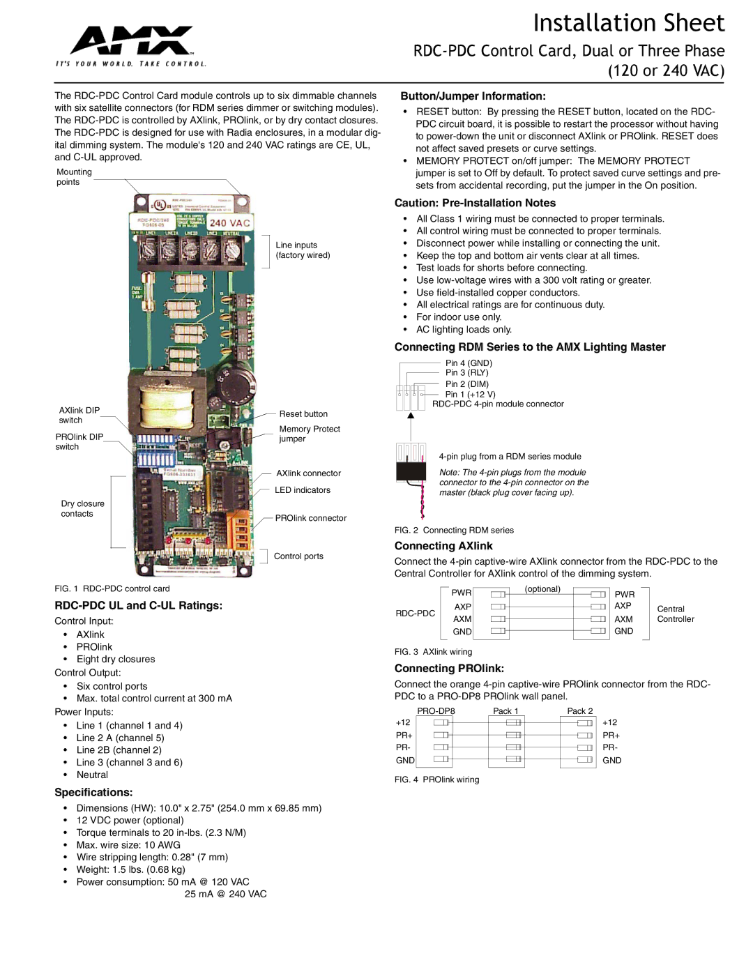
Mounting points
Button/Jumper Information:
•RESET button: By pressing the RESET button, located on the RDC- PDC circuit board, it is possible to restart the processor without having to
•MEMORY PROTECT on/off jumper: The MEMORY PROTECT jumper is set to Off by default. To protect saved curve settings and pre- sets from accidental recording, put the jumper in the On position.
AXlink DIP switch
PROlink DIP switch
Dry closure contacts
Line inputs (factory wired)
Reset button
Memory Protect jumper
AXlink connector
LED indicators
PROlink connector
Control ports
Caution:
•All Class 1 wiring must be connected to proper terminals.
•All control wiring must be connected to proper terminals.
•Disconnect power while installing or connecting the unit.
•Keep the top and bottom air vents clear at all times.
•Test loads for shorts before connecting.
•Use
•Use
•All electrical ratings are for continuous duty.
•For indoor use only.
•AC lighting loads only.
Connecting RDM Series to the AMX Lighting Master
Pin 4 (GND)
Pin 3 (RLY)
Pin 2 (DIM)
Pin 1 (+12 V)
Note: The
FIG. 2 Connecting RDM series
Connecting AXlink
Connect the
FIG. 1 RDC-PDC control card
RDC-PDC UL and C-UL Ratings:
Control Input:
•AXlink
•PROlink
•Eight dry closures Control Output:
•Six control ports
•Max. total control current at 300 mA Power Inputs:
•Line 1 (channel 1 and 4)
•Line 2 A (channel 5)
•Line 2B (channel 2)
•Line 3 (channel 3 and 6)
•Neutral
Specifications:
•Dimensions (HW): 10.0" x 2.75" (254.0 mm x 69.85 mm)
•12 VDC power (optional)
•Torque terminals to 20
•Max. wire size: 10 AWG
•Wire stripping length: 0.28" (7 mm)
•Weight: 1.5 lbs. (0.68 kg)
•Power consumption: 50 mA @ 120 VAC
25 mA @ 240 VAC
|
|
| PWR |
|
|
|
|
|
|
| (optional) |
|
|
|
|
|
|
| PWR |
|
|
|
|
| AXP |
|
|
|
|
|
|
|
|
|
|
|
|
|
|
| AXP |
|
| Central | |
|
|
|
|
|
|
|
|
|
|
|
|
|
|
| ||||||||
|
|
|
|
|
|
|
|
|
|
|
|
|
|
|
|
| AXM |
|
| Controller | ||
|
|
| AXM |
|
|
|
|
|
|
|
|
|
|
|
|
|
|
|
|
| ||
|
|
| GND |
|
|
|
|
|
|
|
|
|
|
|
|
|
|
| GND |
|
|
|
|
|
|
|
|
|
|
|
|
|
|
|
|
|
|
|
|
| |||||
|
|
|
|
|
|
|
|
|
|
|
|
|
|
|
|
|
|
|
|
|
|
|
FIG. 3 AXlink wiring |
|
|
|
|
|
|
|
|
|
|
|
| ||||||||||
Connecting PROlink: |
|
|
|
|
|
|
|
|
|
|
|
| ||||||||||
Connect the orange
| Pack 1 |
| Pack 2 | ||||||||||||||||||
+12 |
|
|
|
|
|
|
|
|
|
|
|
|
|
|
|
|
|
|
| +12 | |
PR+ |
|
|
|
|
|
|
|
|
|
|
|
|
|
|
|
|
|
|
|
| PR+ |
PR- |
|
|
|
|
|
|
|
|
|
|
|
|
|
|
|
|
|
|
|
| PR- |
GND |
|
|
|
|
|
|
|
|
|
|
|
|
|
|
|
|
|
|
|
| GND |
|
|
|
|
|
|
|
|
|
|
|
|
|
|
| |||||||
|
|
|
|
|
|
|
|
|
|
|
|
|
|
|
|
|
|
|
|
|
|
FIG. 4 PROlink wiring |
|
|
|
|
|
|
|
|
|
|
|
|
|
|
| ||||||