Installation Guide
RDM-2DC Dual DC Dimmer Module 1920W, 0-10 VDC (x2)
The
Caution:
• All Class 1 wiring must be connected to proper terminals. | |
• All control wiring must be connected to proper terminals. | |
• | Disconnect power while installing or connecting the unit. |
• | Keep top and bottom air vents clear at all times. |
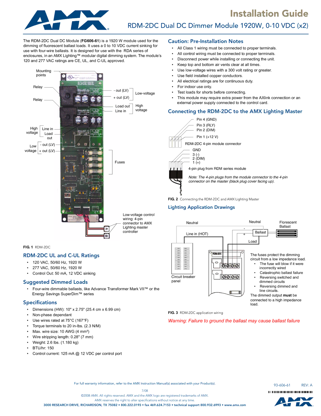
Mounting points
Relay
Relay
High |
|
|
|
|
|
|
|
|
|
| |
| Line in |
|
|
|
|
|
| ||||
voltage |
|
| Load |
|
|
|
|
|
| ||
|
|
|
|
|
|
|
|
|
| ||
|
|
|
| out |
|
| |||||
|
|
|
|
|
| ||||||
|
|
|
|
|
|
| |||||
Low |
| - out (LV) |
|
|
|
| |||||
|
|
| |||||||||
voltage | + out (LV) |
|
|
|
| ||||||
|
|
|
| ||||||||
|
|
|
|
|
|
|
|
|
|
|
|
FIG. 1 RDM-2DC
- out (LV) |
| |
|
| |
+ out (LV) |
| |
|
| High |
Load out | ||
Line in | voltage | |
|
|
|
Fuses
• Use |
• Use field installed copper conductors. |
• All electrical ratings are for continuous duty. |
• For indoor use only. |
• Test loads for shorts before connecting. |
• This module may require extra power from the AXlink connection or an |
external power supply connected to the control card. |
Connecting the RDM-2DC to the AMX Lighting Master
Pin 4 (GND)
Pin 3 (RLY)
Pin 2 (DIM)
Pin 1 (+12 V)
GND 3
2(DIM)
1(+)
Note: The
FIG. 2 Connecting the RDM-2DC and AMX Lighting Master
Lighting Application Drawings
|
|
|
|
|
| Neutral |
|
| Neutral |
|
| Florescent | |||||||||
|
|
|
|
|
|
|
|
|
|
|
|
|
|
|
|
|
|
|
| Ballast | |
|
|
|
|
|
|
|
|
|
|
|
| - |
|
|
|
|
|
| |||
|
|
|
|
|
| Line in (HOT) |
|
|
| Ballast |
|
|
|
| |||||||
|
|
|
|
|
| + |
|
|
|
|
|
|
|
| |||||||
|
|
|
|
|
|
|
|
|
|
|
|
|
|
|
|
|
|
|
|
|
|
|
|
|
|
|
|
|
|
|
|
|
|
|
| Load |
|
|
|
|
| ||
|
|
|
|
|
|
|
|
|
|
|
|
|
|
|
|
|
|
|
|
|
|
|
|
|
|
|
|
|
|
|
|
|
|
|
|
|
|
|
|
|
|
|
|
•120 VAC, 50/60 Hz, 1920 W
•277 VAC, 50/60 Hz, 1920 W
•Control Out: 50 mA, 12 VDC sinking
Suggested Dimmed Loads
•
Specifications
•Dimensions (HW): 10" x 2.75" (25.4 cm x 6.99 cm)
•
•Use wires rated at 75°C (167°F)
•Torque terminals to 20
•Max. wire size: 10 AWG (4 mm²)
•Wire stripping length: 0.28" (7 mm)
•Weight: 2.6 lbs. (1.180 kg)
•BTU/hr: 150
•Control current: 125 mA @ 12 VDC per control port
|
|
|
|
|
| The fuses protect the dimming | |
|
|
|
|
|
| ||
|
|
|
|
|
| circuit from a low impedance load. | |
|
|
|
|
|
| ||
|
|
|
|
|
| • The fuse will blow if it were | |
|
|
|
|
|
| ||
|
|
|
|
|
|
| incorrectly wired |
|
|
|
|
|
|
| |
|
|
|
|
|
| • | Catastrophic ballast failure |
Circuit breaker | • | Reversing switched and | |||||
panel |
| dimmed circuits | |||||
|
|
|
|
|
| • | Reversing dimmed and |
|
|
|
|
|
|
| line circuits. |
The dimmed output must be connected to a high impedance load.
FIG. 3 RDM-2DC application wiring
Warning: Failure to ground the ballast may cause ballast failure
For full warranty information, refer to the AMX Instruction Manual(s) associated with your Product(s). |
| REV: A |
|
7/08
©2008 AMX. All rights reserved. AMX and the AMX logo are registered trademarks of AMX.
AMX reserves the right to alter specifications without notice at any time.
3000 RESEARCH DRIVE, RICHARDSON, TX 75082 • 800.222.0193 • fax 469.624.7153 • technical support 800.932.6993 • www.amx.com