Installation Sheet
RDM-INC Incandescent Dimmer Module 2400 W
The
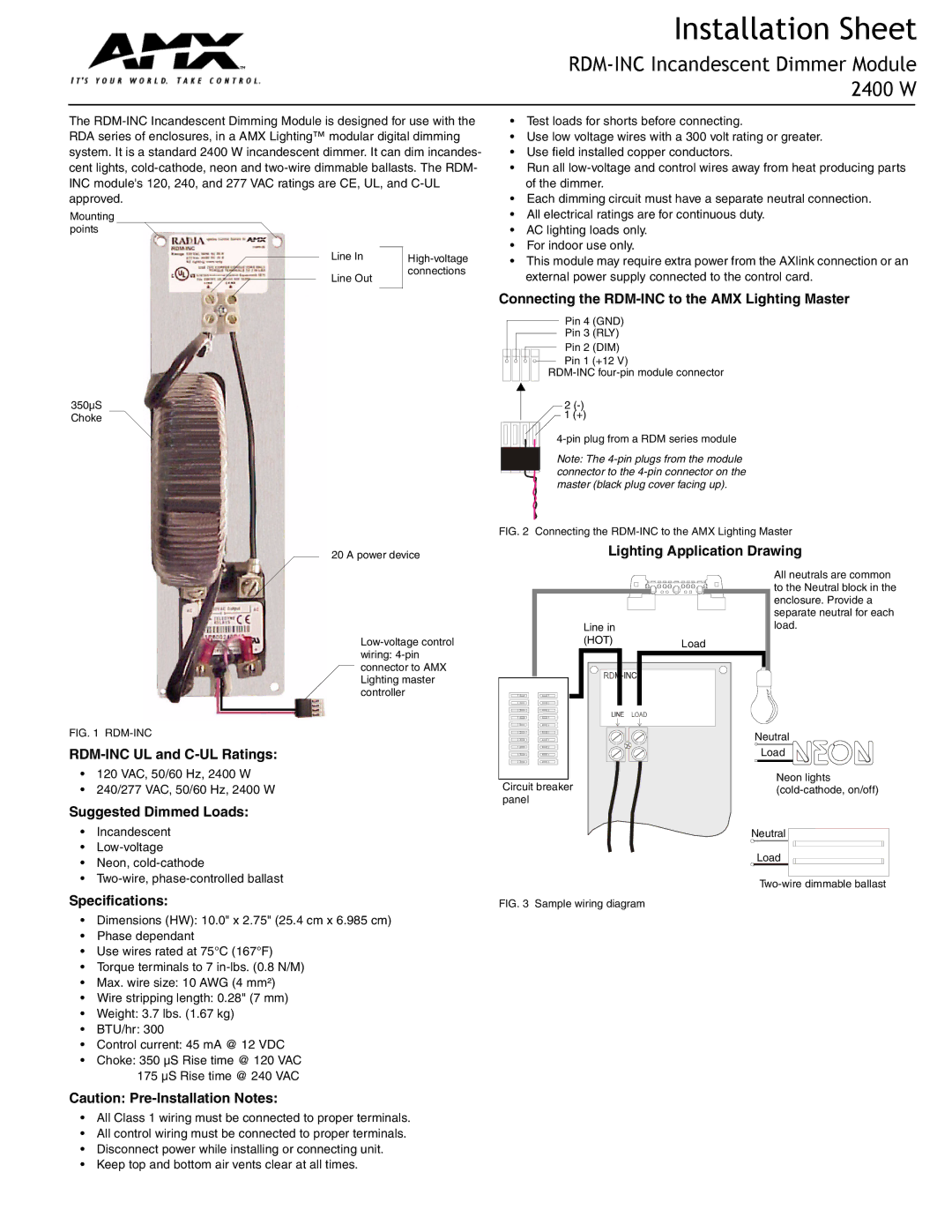
Mounting points
Line In |
| |
Line Out |
| connections |
|
| |
|
|
|
350µS Choke
•Test loads for shorts before connecting.
•Use low voltage wires with a 300 volt rating or greater.
•Use field installed copper conductors.
•Run all
•Each dimming circuit must have a separate neutral connection.
•All electrical ratings are for continuous duty.
•AC lighting loads only.
•For indoor use only.
•This module may require extra power from the AXlink connection or an external power supply connected to the control card.
Connecting the RDM-INC to the AMX Lighting Master
Pin 4 (GND)
Pin 3 (RLY)
Pin 2 (DIM)
Pin 1 (+12 V)
2
1(+)
Note: The
20 A power device
FIG. 1 RDM-INC
•120 VAC, 50/60 Hz, 2400 W
•240/277 VAC, 50/60 Hz, 2400 W
Suggested Dimmed Loads:
•Incandescent
•
•Neon,
•
Specifications:
•Dimensions (HW): 10.0" x 2.75" (25.4 cm x 6.985 cm)
•Phase dependant
•Use wires rated at 75°C (167°F)
•Torque terminals to 7
•Max. wire size: 10 AWG (4 mm²)
•Wire stripping length: 0.28" (7 mm)
•Weight: 3.7 lbs. (1.67 kg)
•BTU/hr: 300
•Control current: 45 mA @ 12 VDC
•Choke: 350 µS Rise time @ 120 VAC
175 µS Rise time @ 240 VAC
FIG. 2 Connecting the RDM-INC to the AMX Lighting Master
Lighting Application Drawing
| All neutrals are common |
| to the Neutral block in the |
| enclosure. Provide a |
| separate neutral for each |
Line in | load. |
(HOT) | Load |
| |
| Neutral |
| Load |
Neon lights
Circuit breaker(cold-cathode, on/off) panel
Neutral
Load
FIG. 3 Sample wiring diagram
Caution:
•All Class 1 wiring must be connected to proper terminals.
•All control wiring must be connected to proper terminals.
•Disconnect power while installing or connecting unit.
•Keep top and bottom air vents clear at all times.