Installing the Motherboard

This manual does not cover CPU, RAM, or expansion card installation.

Please consult the motherboard manual for specific mounting instructions and troubleshooting.

1.Lay the case down with the open side facing up. The drive cages and power supply should be visible.

2.Make sure you have the correct I/O panel for the motherboard. If the panel provided with the case isn’t suitable, please contact the motherboard manufacturer for the correct I/O panel.

3.Line up the motherboard with the standoff holes, and remember which holes are lined up. Not all motherboards will match with all the provided holes; this is normal and won’t affect functionality.

4.Remove the motherboard.

5.Screw the brass standoffs into the threaded holes that line up with the motherboard. Note: Do not over-tighten the standoffs. Some standoffs may be pre-installed for your convenience.

6.Place the motherboard on the brass standoffs.

7.Screw in the motherboard to the standoffs with the provided Philips-head screws. The motherboard is now installed.

Connecting the Power and LED

Picture 1

Picture 2


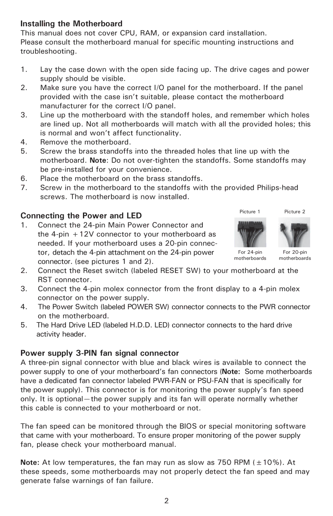
1.Connect the 24-pin Main Power Connector and the 4-pin +12V connector to your motherboard as needed. If your motherboard uses a 20-pin connec-

tor, detach the 4-pin attachment on the 24-pin power

For 24-pin

For 20-pin

connector. (see pictures 1 and 2).

motherboards

motherboards


2.Connect the Reset switch (labeled RESET SW) to your motherboard at the RST connector.

3.Connect the 4-pin molex connector from the front display to a 4-pin molex connector on the power supply.

4.The Power Switch (labeled POWER SW) connector connects to the PWR connector on the motherboard.

5.The Hard Drive LED (labeled H.D.D. LED) connector connects to the hard drive activity header.

Power supply 3-PIN fan signal connector

A three-pin signal connector with blue and black wires is available to connect the power supply to one of your motherboard’s fan connectors (Note: Some motherboards have a dedicated fan connector labeled PWR-FAN or PSU-FAN that is specifically for the power supply). This connector is for monitoring the power supply’s fan speed only. It is optional—the power supply and its fan will operate normally whether this cable is connected to your motherboard or not.

The fan speed can be monitored through the BIOS or special monitoring software that came with your motherboard. To ensure proper monitoring of the power supply fan, please check your motherboard manual.

Note: At low temperatures, the fan may run as slow as 750 RPM (±10%). At these speeds, some motherboards may not properly detect the fan speed and may generate false warnings of fan failure.

2

Page 3
Image 3
Antec 550 user manual Installing the Motherboard, Connecting the Power and LED, Power supply 3-PIN fan signal connector

550 specifications

The Antec 550 is a mid-range power supply unit (PSU) that has garnered attention for its reliability and performance, making it a suitable choice for gamers and PC builders alike. This power supply is designed to meet the demands of modern hardware while maintaining efficiency and stability.

One of the standout features of the Antec 550 is its 80 PLUS Bronze certification. This certification indicates that the PSU operates at an efficiency of up to 85% under typical load conditions, which helps reduce electricity costs and decrease the amount of wasted energy. The improved efficiency not only benefits the user economically but also contributes to lower heat output, enhancing overall system stability and longevity.

The Antec 550 is equipped with a semi-modular cable design. This means that essential cables, such as the motherboard and CPU power connectors, are hardwired, while peripheral connectors can be added as needed. This design allows for easier cable management, resulting in cleaner builds and improved airflow within the case. Additionally, the high-quality cables are crafted with durable materials that ensure flexibility and resilience.

In terms of voltage regulation, the Antec 550 features a single +12V rail design that delivers stable power to the components, reducing the risk of power fluctuations that could lead to hardware failures. This single rail design is particularly beneficial for systems with high-performance GPUs, as it delivers ample power when it’s needed most.

The cooling system in the Antec 550 is also noteworthy. The unit is equipped with a 120mm fan, which operates quietly while delivering efficient cooling performance. This fan uses a intelligent temperature-control mechanism that adjusts the fan speed based on the load, ensuring that the unit remains quiet during low demand periods while ramping up to provide adequate cooling under heavier loads.

Finally, Antec prioritizes user safety with a comprehensive set of protection features. The PSU includes over-voltage, under-voltage, over-current, and short circuit protection, ensuring that both the user and their components are safeguarded against unexpected electrical issues.

Overall, the Antec 550 combines efficiency, modularity, and reliability, making it a solid choice for anyone looking to build or upgrade their gaming rig or workstation. Its thoughtful design and robust features serve to deliver stable power for a variety of computing needs.