Manuals
/
Antec
/
Computer Equipment
/
Computer Hardware
Antec
III 500 CONNECTING THE eSATA PORT, CONNECTING THE AUDIO PORTS AC’ 97 and HDA, Signal Names
Models:
III 500
1
4
7
7
Download
7 pages
3.69 Kb
1
2
3
4
5
6
7
Specs
Install
Signal Names
Setting Up
Page 4
Image 4
Page 3
Page 5
Page 4
Image 4
Page 3
Page 5
Contents
Sonata III
User’s Manual
Manuel de l’utilisateur Anwenderhandbuch Manuale per l’operatore
Manual del usuario
Disclaimer
SETTING UP
SONATA III 500 USER’S MANUAL
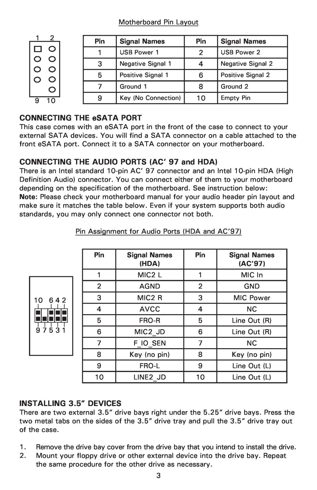
CONNECTING THE USB PORTS
INSTALLING THE MOTHERBOARD
Connecting the Power and LED
CONNECTING THE eSATA PORT
CONNECTING THE AUDIO PORTS AC’ 97 and HDA
INSTALLING 3.5” DEVICES
Signal Names
5.25” DEVICE INSTALLATION
COOLING SYSTEM The Rear Exhaust TriCool fan
Specifications
The Front 120mm Fan
MAINTAINING THE WASHABLE AIR FILTER
To remove the filter
Antec, Inc
Antec Europe B.V
Customer Support US & Canada
Europe
Top
Page
Image
Contents