INSTALLING THE MOTHERBOARD
This manual does not cover CPU, RAM, or expansion card installation. Please consult your motherboard manual for specific mounting instructions and troubleshooting.
1.Lay the case down, with the open side facing up. The drive cages and power supply should be visible.
2.Make sure you have the correct I/O panel for your motherboard. If the panel provided with the case isn’t suitable, please contact your motherboard manufacturer for the correct I/O panel.
3.Line up your motherboard with the standoff holes, and remember which holes are lined up. Not all motherboards will match with all the provided holes; this is normal, and won’t affect functionally. (In other words, there will likely be extra holes.)
4.Remove your motherboard by lifting it up.
5.Screw the brass standoffs into the threaded holes that line up with your motherboard. Do not
6.Place your motherboard on the brass standoffs.
7.Screw in your motherboard to the standoffs with the provided
Connecting the Power and LED
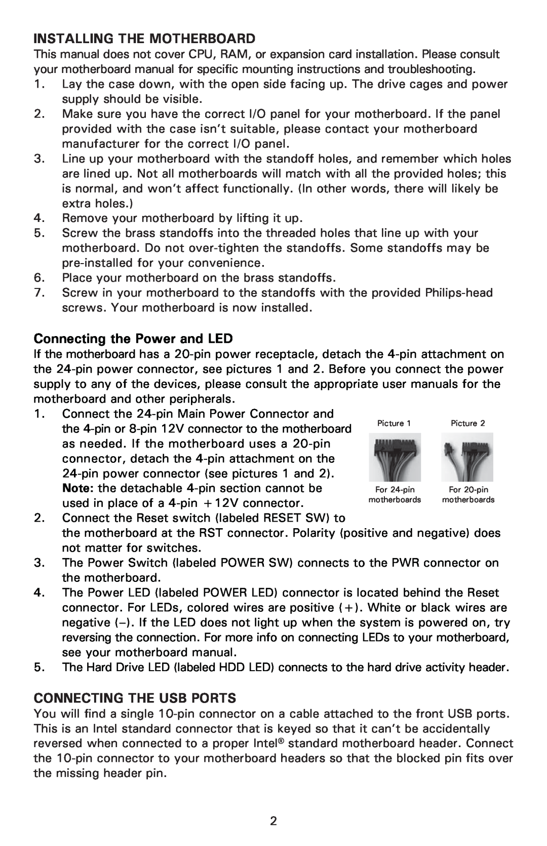
If the motherboard has a
1. Connect the
the | Picture 1 | Picture 2 |
|
| |
as needed. If the motherboard uses a |
|
|
connector, detach the |
|
|
|
| |
Note: the detachable | For | For |
used in place of a | motherboards | motherboards |
|
|
2.Connect the Reset switch (labeled RESET SW) to
the motherboard at the RST connector. Polarity (positive and negative) does not matter for switches.
3.The Power Switch (labeled POWER SW) connects to the PWR connector on the motherboard.
4.The Power LED (labeled POWER LED) connector is located behind the Reset connector. For LEDs, colored wires are positive (+). White or black wires are negative
5.The Hard Drive LED (labeled HDD LED) connects to the hard drive activity header.
CONNECTING THE USB PORTS
You will find a single
2