2.4INTERNAL 2.5” DEVICE INSTALLATION
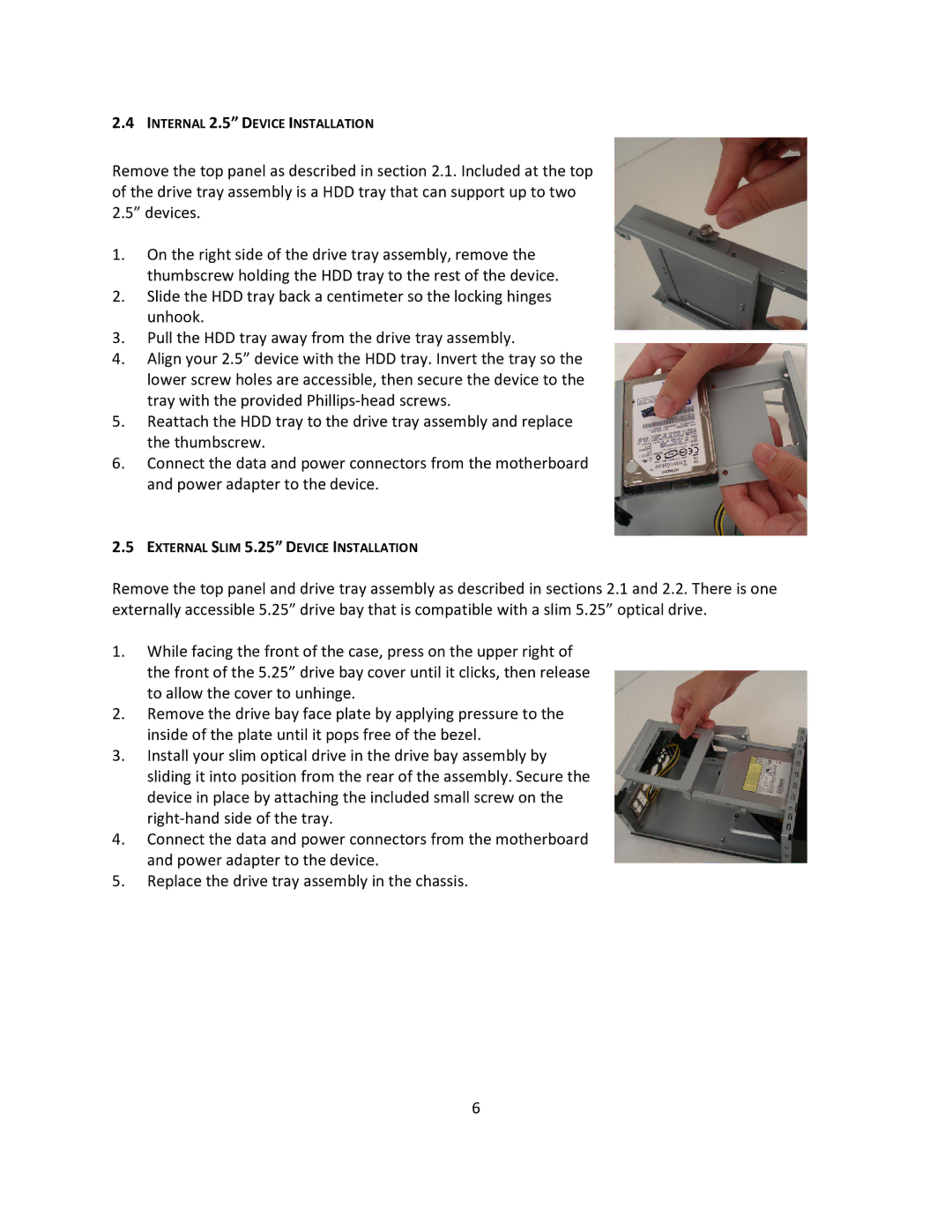
Remove the top panel as described in section 2.1. Included at the top of the drive tray assembly is a HDD tray that can support up to two 2.5” devices.
1.On the right side of the drive tray assembly, remove the thumbscrew holding the HDD tray to the rest of the device.
2.Slide the HDD tray back a centimeter so the locking hinges unhook.
3.Pull the HDD tray away from the drive tray assembly.
4.Align your 2.5” device with the HDD tray. Invert the tray so the lower screw holes are accessible, then secure the device to the tray with the provided
5.Reattach the HDD tray to the drive tray assembly and replace the thumbscrew.
6.Connect the data and power connectors from the motherboard and power adapter to the device.
2.5EXTERNAL SLIM 5.25” DEVICE INSTALLATION
Remove the top panel and drive tray assembly as described in sections 2.1 and 2.2. There is one externally accessible 5.25” drive bay that is compatible with a slim 5.25” optical drive.
1.While facing the front of the case, press on the upper right of the front of the 5.25” drive bay cover until it clicks, then release to allow the cover to unhinge.
2.Remove the drive bay face plate by applying pressure to the inside of the plate until it pops free of the bezel.
3.Install your slim optical drive in the drive bay assembly by sliding it into position from the rear of the assembly. Secure the device in place by attaching the included small screw on the
4.Connect the data and power connectors from the motherboard and power adapter to the device.
5.Replace the drive tray assembly in the chassis.
6
