CONNECTING THE FRONT I/O PORTS
3.1 USB 2.0
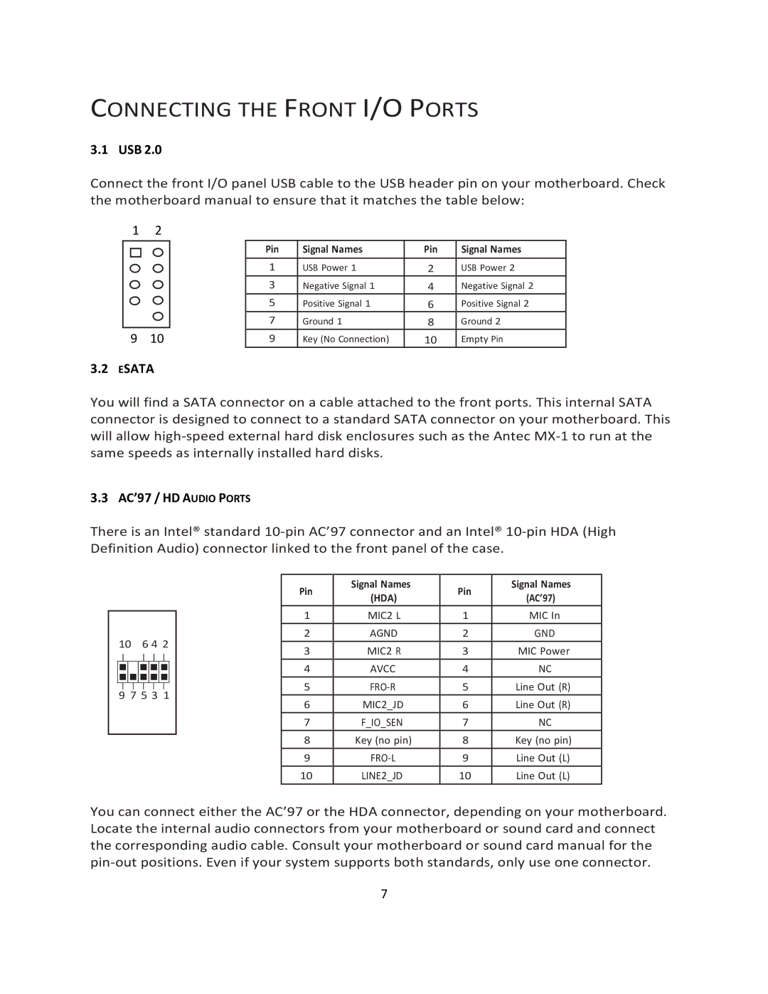
Connect the front I/O panel USB cable to the USB header pin on your motherboard. Check the motherboard manual to ensure that it matches the table below:
1 | 2 |
|
|
|
|
|
| Pin | Signal Names | Pin | Signal Names |
|
| 1 | USB Power 1 | 2 | USB Power 2 |
|
| 3 | Negative Signal 1 | 4 | Negative Signal 2 |
|
| 5 | Positive Signal 1 | 6 | Positive Signal 2 |
|
| 7 | Ground 1 | 8 | Ground 2 |
9 | 10 | 9 | Key (No Connection) | 10 | Empty Pin |
3.2 ESATA
You will find a SATA connector on a cable attached to the front ports. This internal SATA connector is designed to connect to a standard SATA connector on your motherboard. This will allow
3.3 AC’97 / HD AUDIO PORTS
There is an Intel® standard
106 4 2
9 7 5 3 1
Pin
1
2
3
4
5
6
7
8
9
10
Signal Names (HDA)
MIC2 L
AGND
MIC2 R
AVCC
MIC2_JD
F_IO_SEN Key (no pin)
Pin
1
2
3
4
5
6
7
8
9
10
Signal Names (AC’97)
MIC In
GND
MIC Power
NC
Line Out (R) Line Out (R)
NC
Key (no pin) Line Out (L) Line Out (L)
You can connect either the AC’97 or the HDA connector, depending on your motherboard. Locate the internal audio connectors from your motherboard or sound card and connect the corresponding audio cable. Consult your motherboard or sound card manual for the
7