3.Line up your motherboard with the standoff holes, and remember which holes are lined up. Not all motherboards will match with all the provided holes; this is normal, and won't affect functionally. (In other words, there will likely be extra holes.)
4.Remove your motherboard by lifting it up.
5.Screw the brass standoffs into the threaded holes that line up with your motherboard. Do not overtighten the standoffs. Some standoffs may be
6.Place your motherboard on the brass standoffs.
7.Screw in your motherboard to the standoffs with the provided
CONNECTING THE POWER AND LED
The power supply conforms to the latest ATX12V Version 2.0 standard. It is also
The power supply is also equipped with a
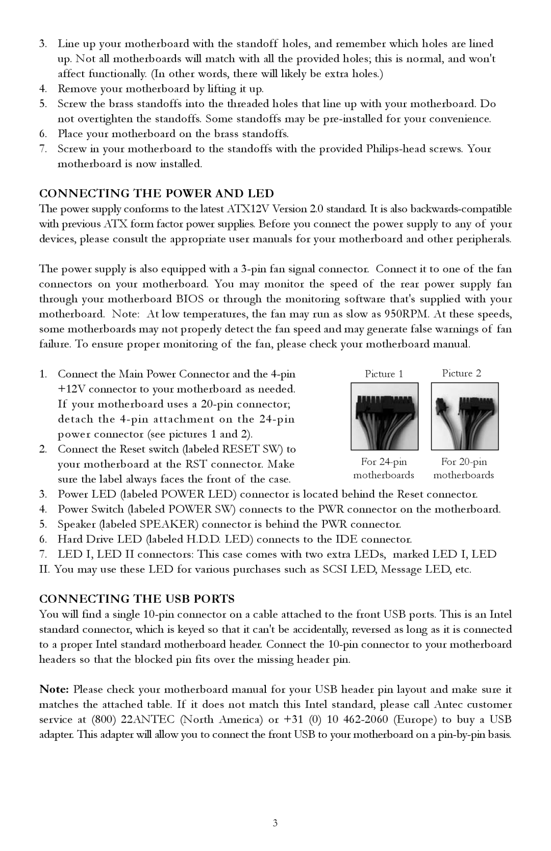
1. | Connect the Main Power Connector and the | Picture 1 |
| Picture 2 |
| +12V connector to your motherboard as needed. |
|
|
|
|
|
|
| |
| If your motherboard uses a |
|
|
|
| detach the |
|
|
|
| power connector (see pictures 1 and 2). |
|
|
|
2. | Connect the Reset switch (labeled RESET SW) to |
|
|
|
For |
| For | ||
| your motherboard at the RST connector. Make |
| ||
| sure the label always faces the front of the case. | motherboards |
| motherboards |
3.Power LED (labeled POWER LED) connector is located behind the Reset connector.
4.Power Switch (labeled POWER SW) connects to the PWR connector on the motherboard.
5.Speaker (labeled SPEAKER) connector is behind the PWR connector.
6.Hard Drive LED (labeled H.D.D. LED) connects to the IDE connector.
7.LED I, LED II connectors: This case comes with two extra LEDs, marked LED I, LED II. You may use these LED for various purchases such as SCSI LED, Message LED, etc.
CONNECTING THE USB PORTS
You will find a single
Note: Please check your motherboard manual for your USB header pin layout and make sure it matches the attached table. If it does not match this Intel standard, please call Antec customer service at (800) 22ANTEC (North America) or +31 (0) 10
3